

DLegu.1
Associate II
February 5, 2020
Solved

Stm32f405 unable to enter DFU

  • February 5, 2020
  • 5 replies
  • 5193 views

I have designed my custom stm32f405 board based on Pyboard 1.1 and Adafruit Feather stm32F4 Express and was unable to enter USB DFU with it.

I uploaded the code using ST-Link and can confirm that USB OTG FS works, without DFU the device is visible as Serial COM Port and works fine. Code I am using is built in Stm32CubeIDE.

Unfortunately shorting BOOT0 pin with 3.3V leaves the board in reset loop and no device is detected by the computer. Microcontroller does not even enter DFU mode because when the connection is removed the code is executed just after.

Additionally when BOOT0 is on 3.3V, PB13 pin is high for some reason (I have LED attached there), I couldn't find any information about that.

I checked all the connections in schematic and I am almost sure everything is correct.

So far I tried:

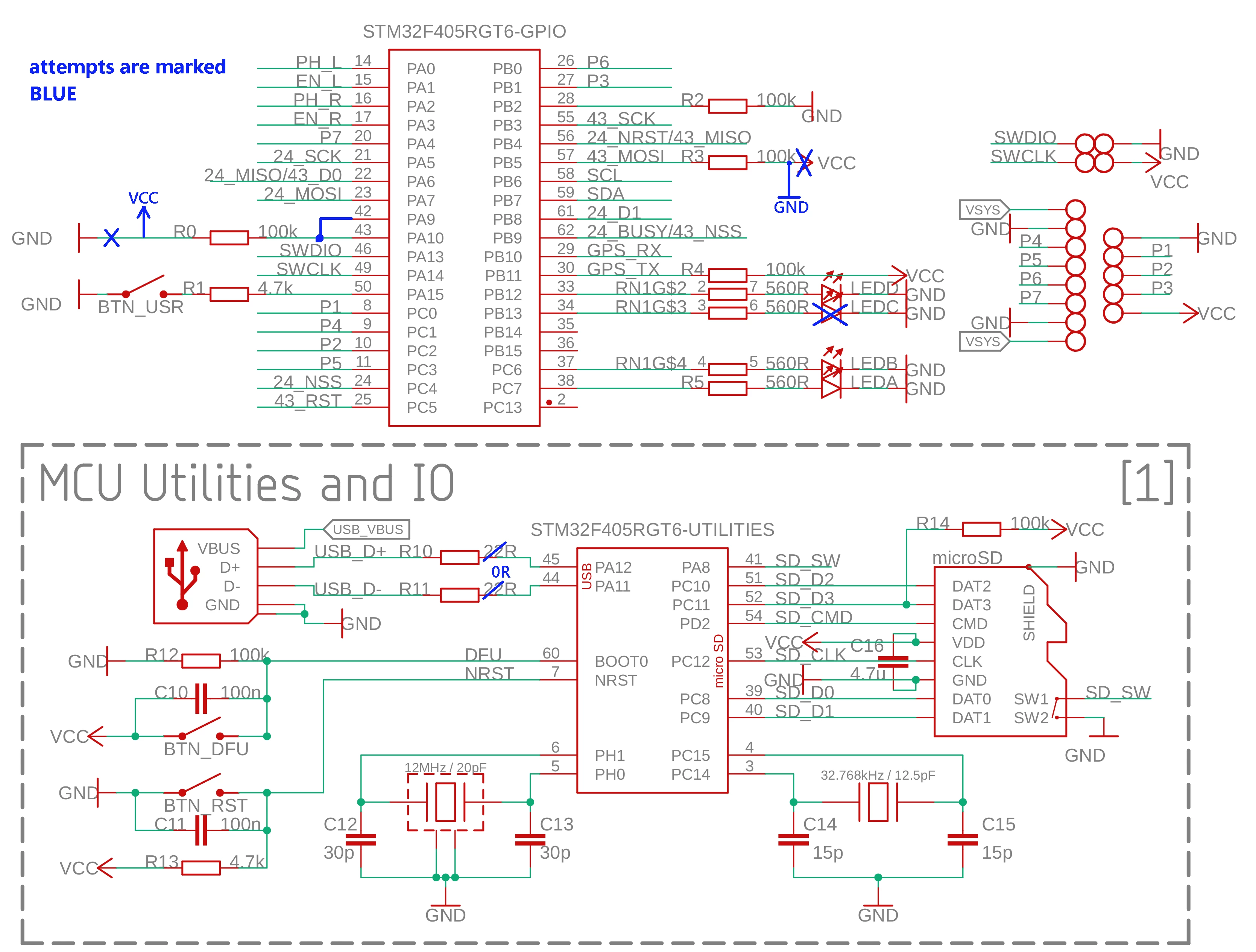
  • different pulls on PC11 (up), PA10 (up and down), PB5 (up and down), PB11 (up) and PB2 (down)
  • pull-up on PA9 if VBUS sensing was somehow activated (not in my code)
  • desoldering LED that lits up

I really have no clue what to do now, everything works fine but not the DFU. My board implements many peripherials but that probably isn't the case.

Here is a part of my schematic with the things I have tried so far.
0690X00000ByaESQAZ.png

Schematics I have referenced to:

Pyboard: http://micropython.org/resources/PYBv11-schematics.pdf

Adafruit Feather: https://cdn-learn.adafruit.com/assets/assets/000/083/680/original/feather_boards_schem.png?1573012880

This topic has been closed for replies.
Best answer by Andrei Chichak

What clive1 said, does your 12 MHz crystal start/stabilize quickly?

We just went through this same thing on a 405VGT6 board where it would not go into DFU mode. We tried a whole lot of things, then I noticed that when I put an oscilloscope probe on the crystal, I'd get a blip every 256ms for a very short time. Zooming in, it showed that around 6ms (?) in my crystal would just be starting to oscillate and the power would be turned off. Our 16MHz crystal wouldn't start fast enough, and recalculating the components showed that it wasn't going to start fast enough in DFU mode, but would start eventually in normal running. Reverting back to an 8MHz crystal its resistor and capacitors, from another design and - BAM - 100% stable DFU.

Recalculate your series resistance and load capacitances with your chosen crystal.

As you've seen, you need PA9/10 tied one way or the other for VBUS and USB_ID detect, but those can just be tied high/low according to the docs. You're on PA11/12, so that should be okay.

5 replies

Tesla DeLorean
Guru
February 5, 2020

AN2606

https://www.st.com/content/ccc/resource/technical/document/application_note/b9/9b/16/3a/12/1e/40/0c/CD00167594.pdf/files/CD00167594.pdf/jcr:content/translations/en.CD00167594.pdf

PB13 is CAN2_TX

PB10/PB11 could be problematic if the GPS starts chattering immediately.

Remember the boot loader is not looking for the 0x7F pattern on the USART, it is measuring pulses with a TIM to try and determine a baud rate for the signals it sees

Tips, Buy me a coffee, or three.. PayPal Venmo (See Profile) Up vote any posts that you find helpful, it shows what's working..
DLegu.1
DLegu.1Author
Associate II
February 5, 2020

Thanks for a reply!

I will try to isolate / disable the gps to be sure.

According to the AN2606 the bootloader checks for USB cable > page 105 ("USB cable detected").

Where I can find information about this routine?

Tesla DeLorean
Guru
February 5, 2020

Not sure they go into specific detail. AN2606 says it doesn't need a pull-up

My expectation is it will be looking at signal transitions on other interfaces first.

If it detects signals/levels on DP+ it will then go quantify the HSE clock, and then come up in USB mode.

You might want to look at the System Loader USB/DFU docs, I've only spent time on the USART / CAN protocol descriptions.

Does your 12 MHz crystal start/stabilize quickly?

Tips, Buy me a coffee, or three.. PayPal Venmo (See Profile) Up vote any posts that you find helpful, it shows what's working..
Andrei Chichak
Andrei ChichakBest answer
Lead
February 5, 2020

What clive1 said, does your 12 MHz crystal start/stabilize quickly?

We just went through this same thing on a 405VGT6 board where it would not go into DFU mode. We tried a whole lot of things, then I noticed that when I put an oscilloscope probe on the crystal, I'd get a blip every 256ms for a very short time. Zooming in, it showed that around 6ms (?) in my crystal would just be starting to oscillate and the power would be turned off. Our 16MHz crystal wouldn't start fast enough, and recalculating the components showed that it wasn't going to start fast enough in DFU mode, but would start eventually in normal running. Reverting back to an 8MHz crystal its resistor and capacitors, from another design and - BAM - 100% stable DFU.

Recalculate your series resistance and load capacitances with your chosen crystal.

As you've seen, you need PA9/10 tied one way or the other for VBUS and USB_ID detect, but those can just be tied high/low according to the docs. You're on PA11/12, so that should be okay.

DLegu.1
DLegu.1Author
Associate II
February 11, 2020

Yes! It worked, thank you very much. Lowering capacitance of crystal capacitors solved the problem. Manufacturer stated that stray capacitance is 20pF but it seems to be much lower.​