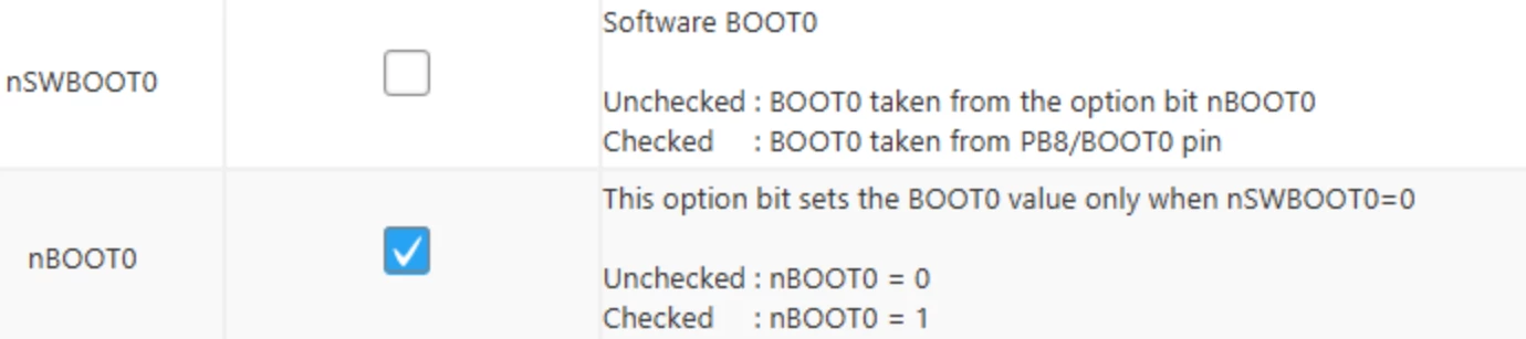
Are ‘BOOT0’ and ‘nBOOT0’ different? As it stands, the programmer requires a value of ‘0’ to boot from FLASH, but the table wants a value of ‘1’. Is the value referenced by nBOOT1 the inverse of the value set in nBOOT0?
BOOT0 is the name of the physical MCU pin. nBOOT0, nBOOT1, nSWBOOT0 are the names of the bits in option byte register, all three are dedicated bits.
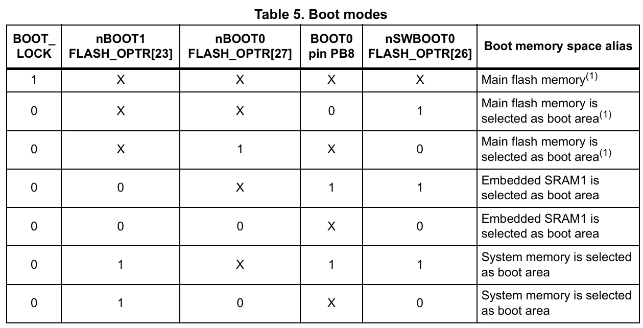
“Main flash memory” is the location of the user firmware. “System memory” is the STM32 internal bootloader code, cannot be changed.
boot0 is a condition that can be controlled either by physical pin or by register bit. This condition selects what will run after reset, either user firmware or system bootloader, both are in flash memory.
boot1 is an additional condition that selects between flash and sram1 memory. This mostly comes from the register bit, but older series like F1 used to have this as a physical pin as well.
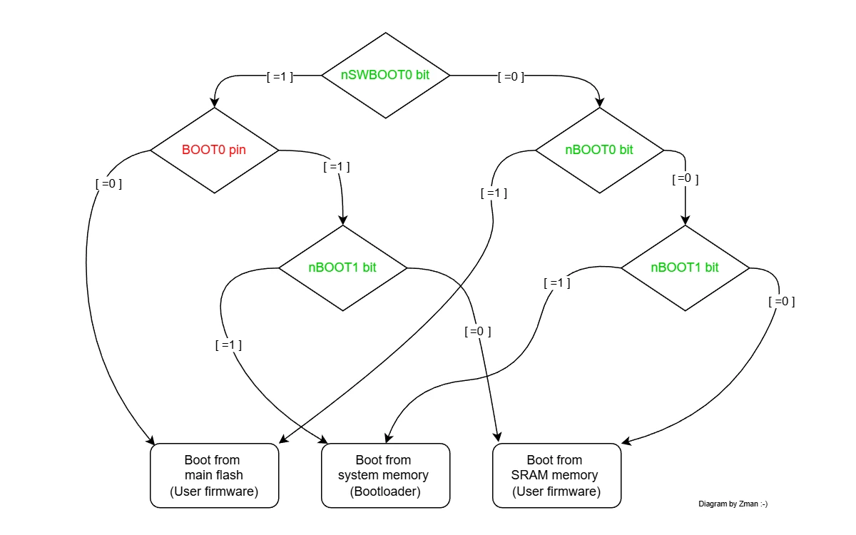
Basically, if your nSWBOOT0 bit is set (=1, and this is by default) then boot0 option is taken from the physical pin (BOOT0). If you do not want the hardware pin to control the boot0 option, you may clear the nSWBOOT0 bit (=0). Once this is done, the boot0 option is controlled by nBOOT0 bit. Set it to 1 for user firmware, clear to start with bootloader.
Controlling boot1 is more rare, but it can be used in special cases if you want to run from SRAM while updating whole flash.
Check the AN2606 Appnote for more details, especially Table 6.
BOOT0 is the name of the physical MCU pin. nBOOT0, nBOOT1, nSWBOOT0 are the names of the bits in option byte register, all three are dedicated bits.
“Main flash memory” is the location of the user firmware. “System memory” is the STM32 internal bootloader code, cannot be changed.
boot0 is a condition that can be controlled either by physical pin or by register bit. This condition selects what will run after reset, either user firmware or system bootloader, both are in flash memory.
boot1 is an additional condition that selects between flash and sram1 memory. This mostly comes from the register bit, but older series like F1 used to have this as a physical pin as well.
Basically, if your nSWBOOT0 bit is set (=1, and this is by default) then boot0 option is taken from the physical pin (BOOT0). If you do not want the hardware pin to control the boot0 option, you may clear the nSWBOOT0 bit (=0). Once this is done, the boot0 option is controlled by nBOOT0 bit. Set it to 1 for user firmware, clear to start with bootloader.
Controlling boot1 is more rare, but it can be used in special cases if you want to run from SRAM while updating whole flash.
Check the AN2606 Appnote for more details, especially Table 6.
Thanks, that diagram explains it much better than the documentation - would be a useful addition 😉
It shows very clearly that the “BOOT0” referenced in the comment against “nBOOT1” in CubeProgrammer shows the levels when the BOOT0 pin is being used. I think it would be helpful if the fact that the values are the other way round when “nBOOT0” is being used could be highlighted.
All posts are made in a personal capacity. MISRA C++ Chair, MISRA C WG Member, Director The MISRA Consortium Limited (TMCL)