STM32C542 Development (6) — DAC Fixed-Voltage Output
Overview
This chapter introduces how to use the on-chip DAC of the STM32C5 to generate a fixed analog voltage output. The STM32C5 DAC supports 12-bit/8-bit resolution, external pin output, output buffering, and DMA. In 12-bit mode, the digital input range is 0 to 4095.
In this experiment, DAC1 Channel 1 is used, with the analog voltage output through PA4 (DAC1_OUT1). The program calculates the DAC digital value according to the reference voltage and the target output voltage, sets the conversion data using HAL_DAC_SetChannelData(), and then starts the DAC output using HAL_DAC_StartChannel().
Hardware Preparation
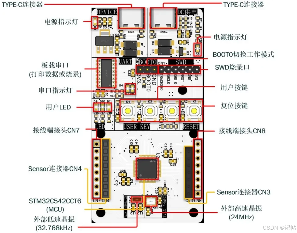
First, prepare a development board. In this example, I use a self-designed development board. Samples can be requested if needed.
The main MCU is STM32C542CCT6.
Reference Code
GitHub:
https://github.com/CoreMaker-lab/STM32C542_SENSOR
Creating a Project with STM32CubeMX2
In this example, STM32CubeMX2 is used to generate the project, with STM32C542CCT6 selected as the target MCU.
Open STM32CubeMX2 and enter the Home page.
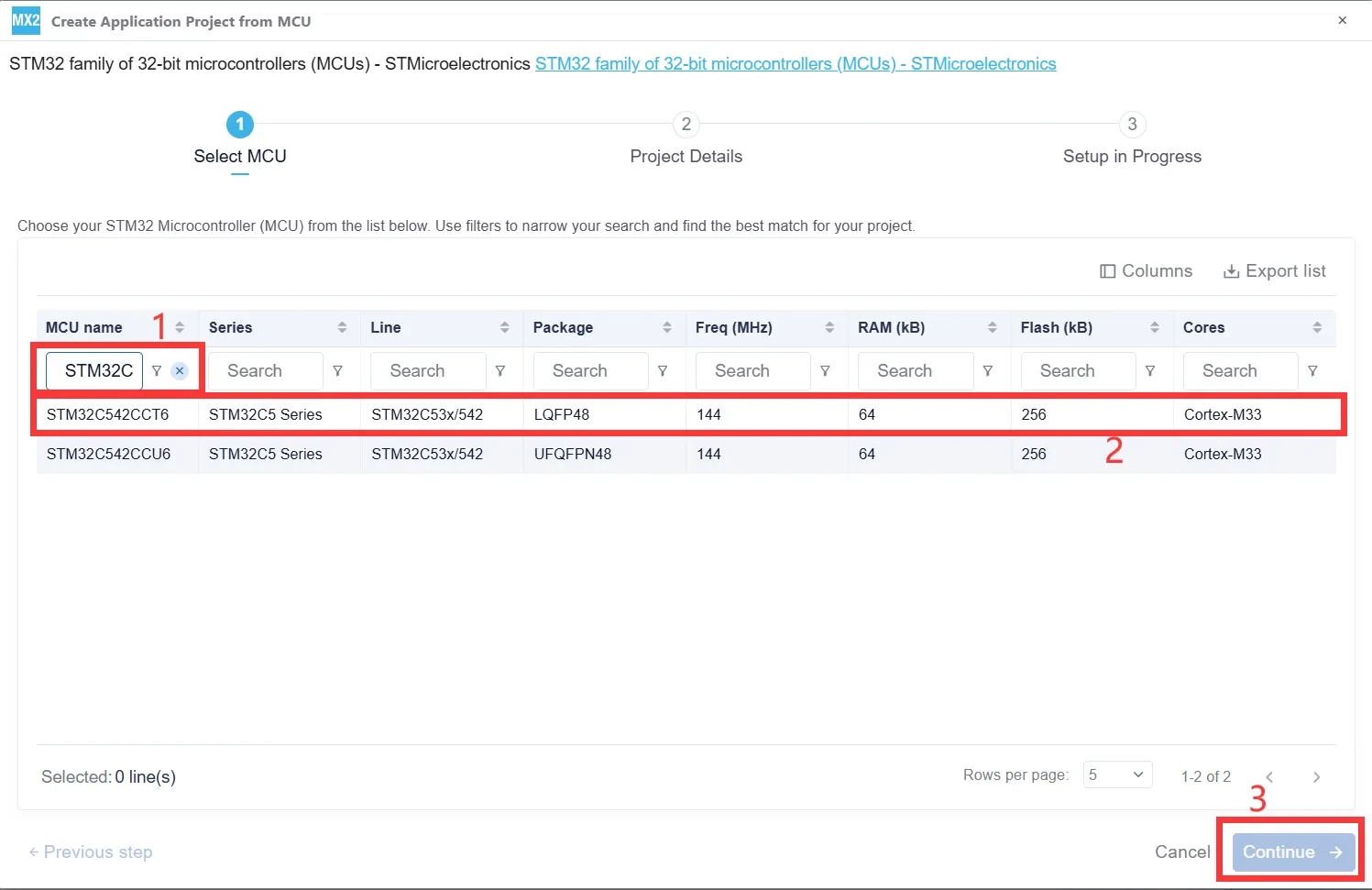
Click MCU to create a new project based on a specific MCU part number.
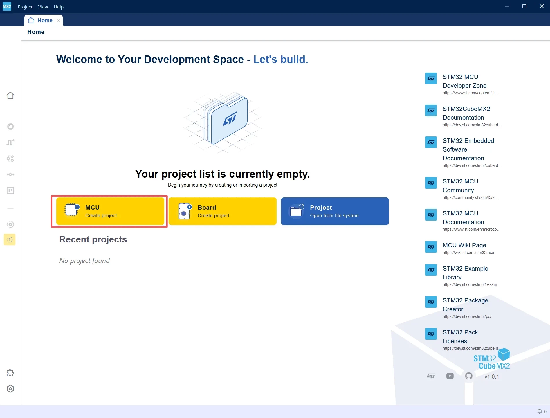
Enter STM32C542CCT6 in the MCU name field. Select the corresponding STM32C5 device, and then click Continue to proceed to the next step of project configuration.
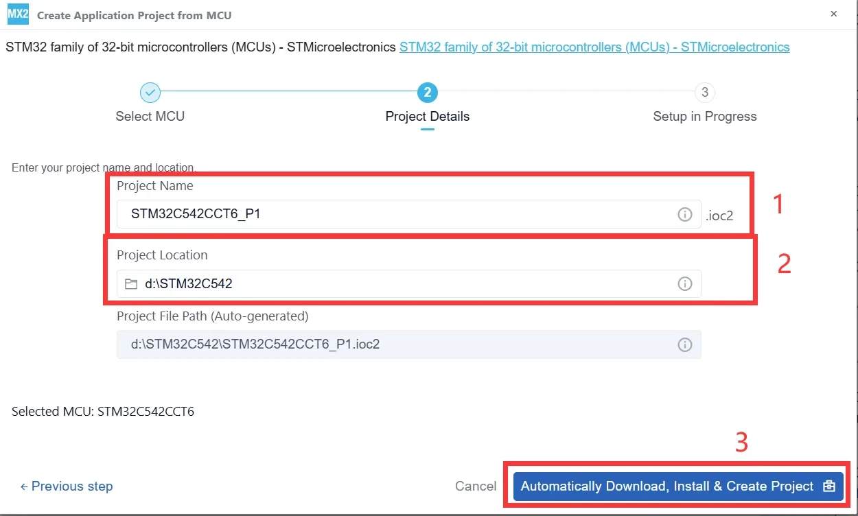
After entering the project name and save path, click “Automatically Download, Install & Create Project”. STM32CubeMX2 will automatically download the required software package and create the project.
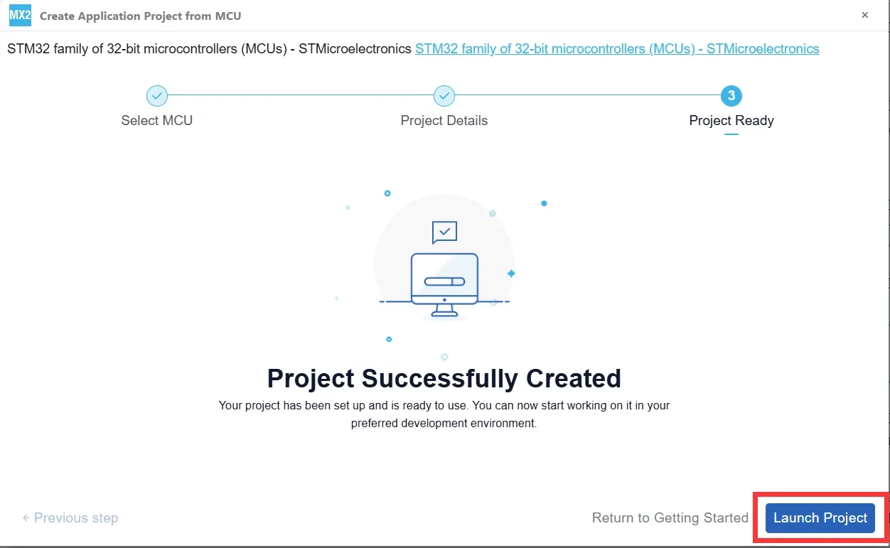
When STM32CubeMX2 displays “Project Successfully Created”, click “Launch Project” in the lower-right corner to enter the project configuration interface.
Clock Tree Configuration
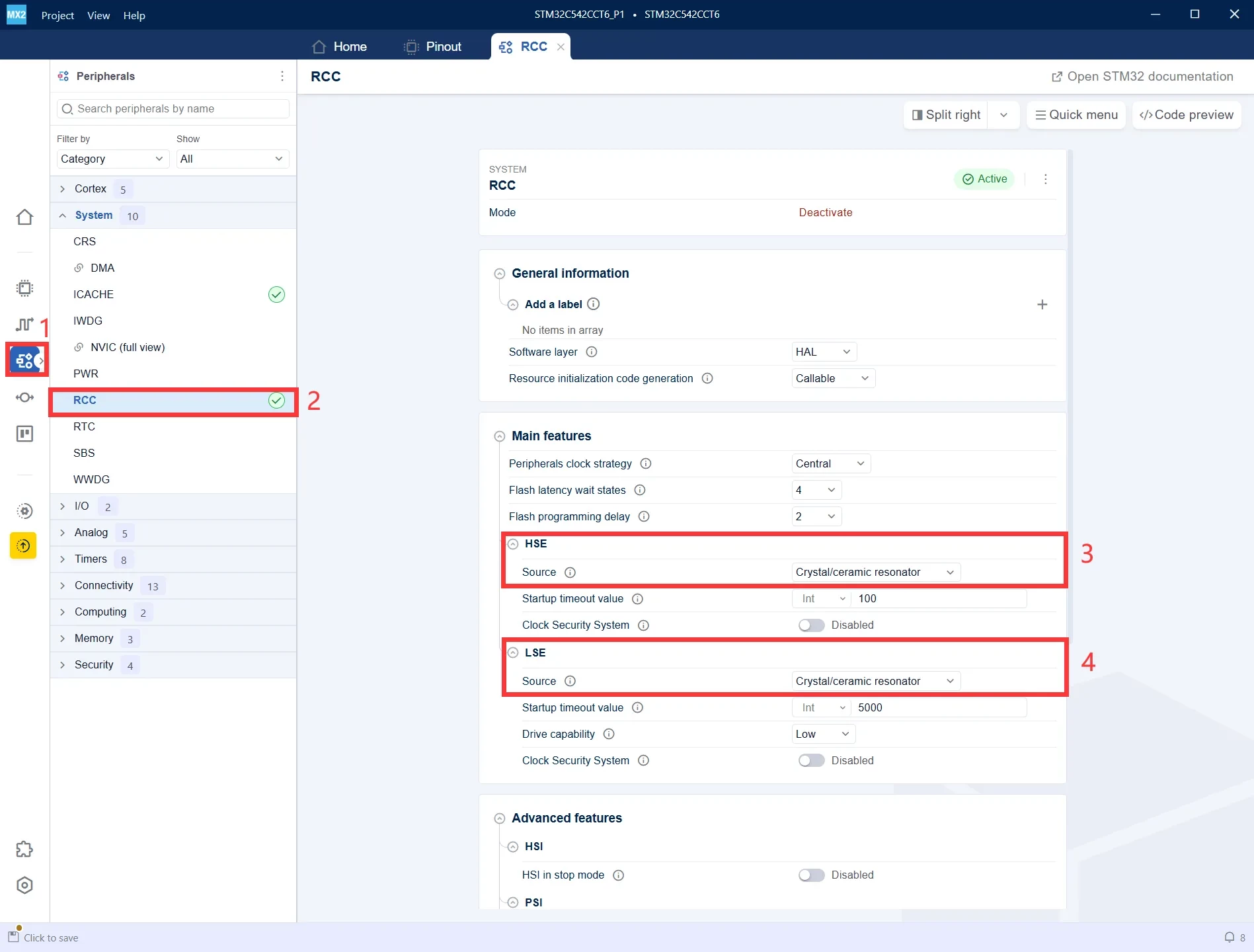
- Click the Peripherals configuration entry on the left to open the peripheral configuration interface.
- Under the System category, select RCC to configure the system clock sources.
- Set HSE Source to Crystal/ceramic resonator to enable the external high-speed crystal oscillator.
- Set LSE Source to Crystal/ceramic resonator to enable the external low-speed crystal oscillator.
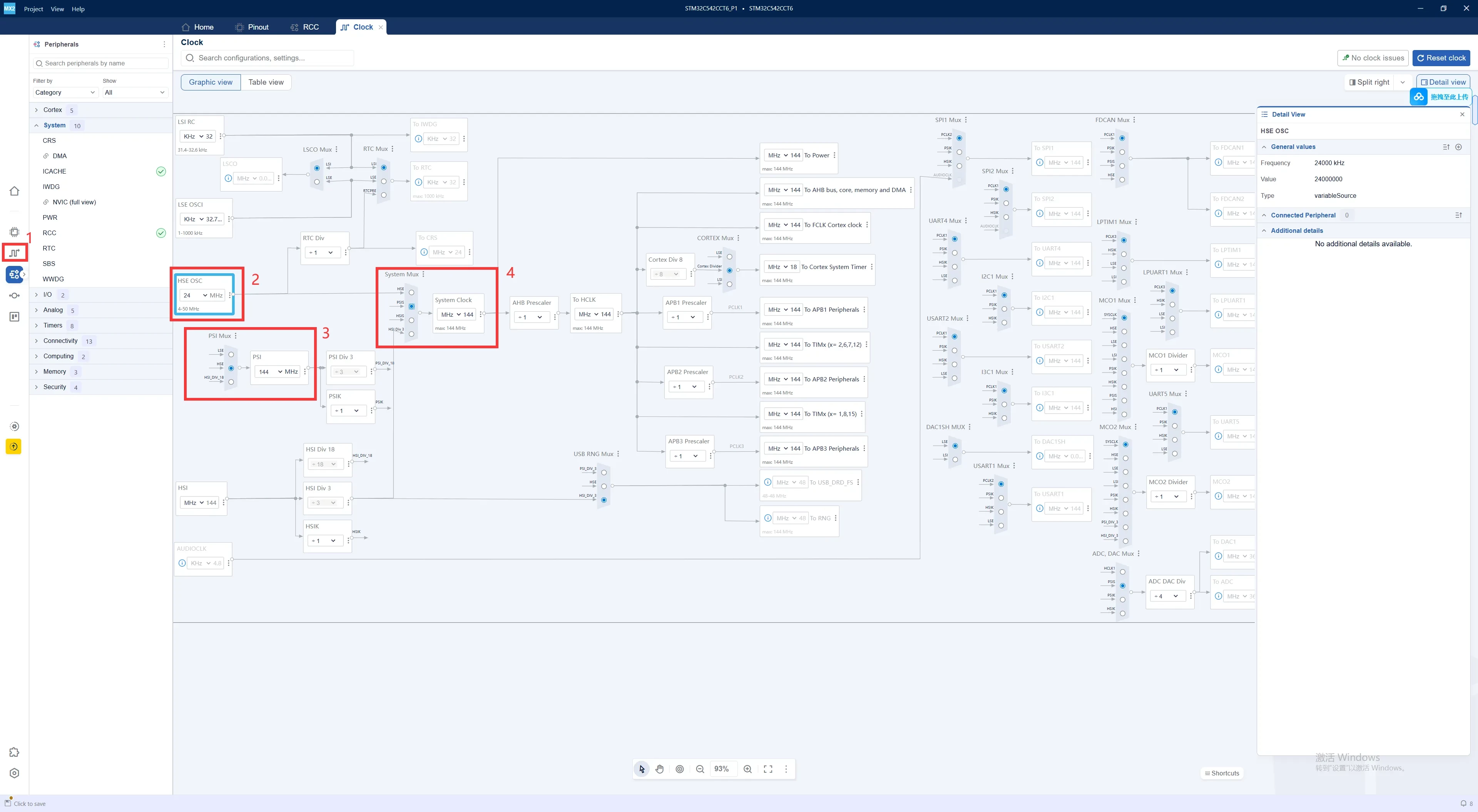
- Click the Clock icon on the left to enter the clock tree configuration interface.
- HSE OSC: Set the external high-speed crystal frequency. In this example, it is configured to 24 MHz.
- PSI Mux / PLL: Select and configure the PLL clock source to generate the required system frequency.
- System Mux: Select the system clock source. In this example, the system clock is configured to 144 MHz.
DEBUG Configuration
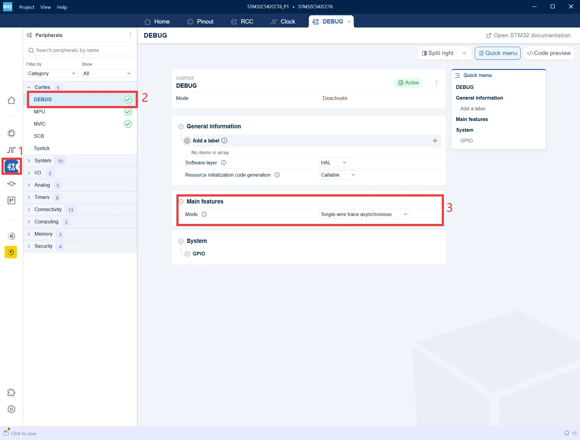
In Peripherals, select Cortex → DEBUG, and set Mode to Single-wire trace asynchronous. This enables subsequent program downloading, online debugging, and Trace debugging functions.
UART Configuration
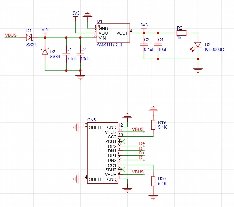
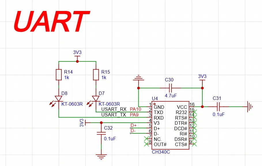
According to the schematic, PA9 and PA10 are used as the UART pins on the development board.
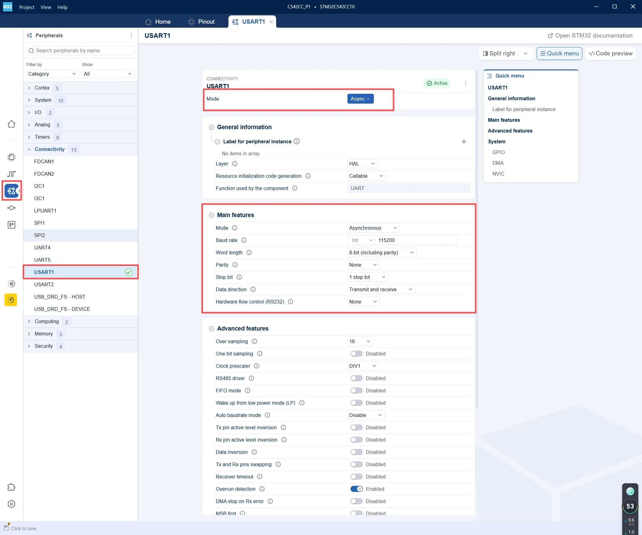
- In Peripherals, select Connectivity → USART1.
- Set Mode to Async to configure USART1 in asynchronous mode.
- Function used by the component is shown as UART, indicating that USART1 uses the UART HAL driver in asynchronous mode.
- Configure the UART parameters as follows: 115200 baud rate, 8 data bits, no parity, 1 stop bit, and transmit/receive mode.
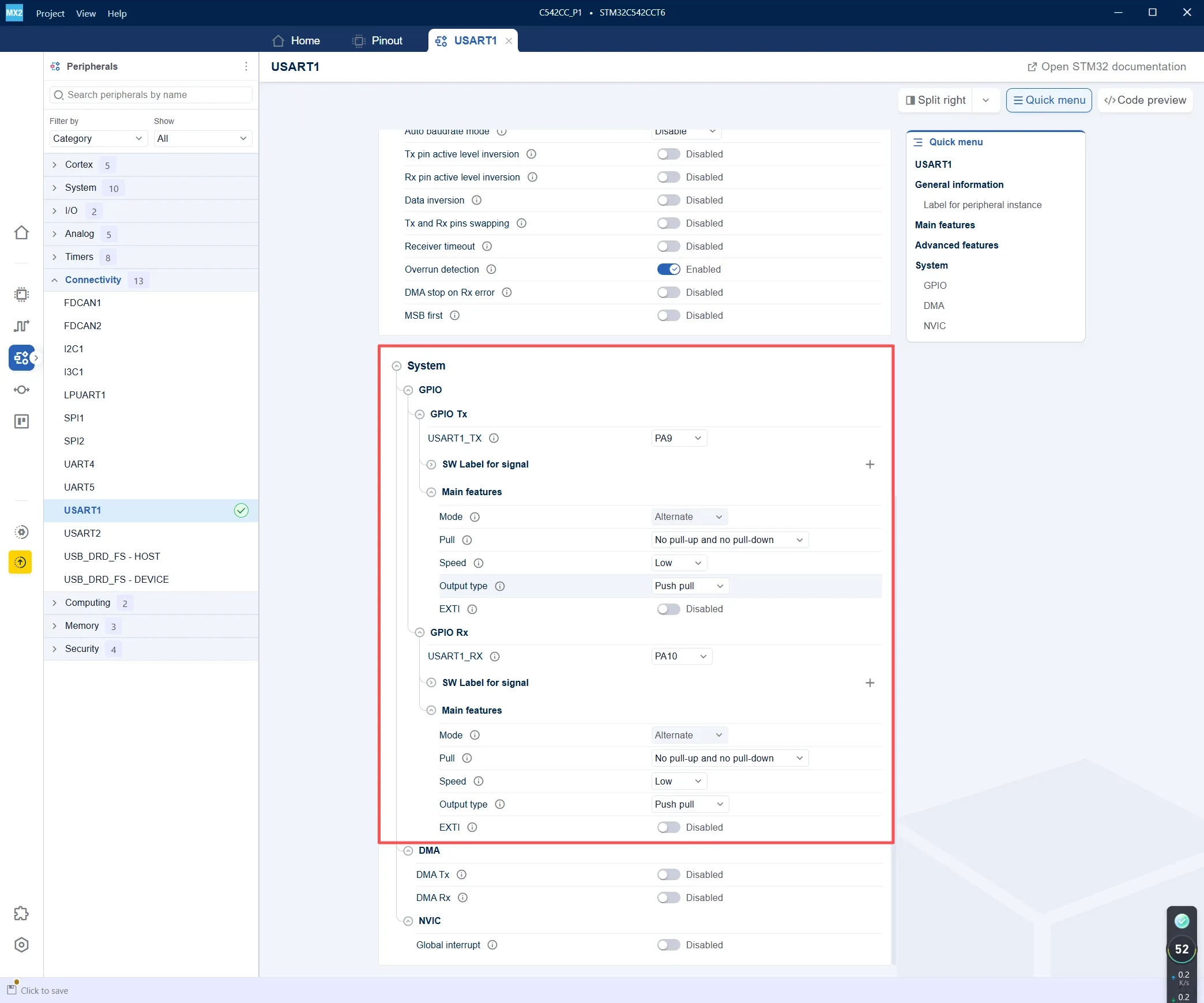
- GPIO Tx: Select PA9 for USART1_TX.
- GPIO Rx: Select PA10 for USART1_RX.
- Configure both PA9 and PA10 in Alternate Function mode.
- Set Pull to No pull-up and no pull-down, Output type to Push pull, and Speed to Low.
DAC Configuration
Open STM32CubeMX2 and enter the DAC peripheral configuration interface. Configure DAC1 as follows:
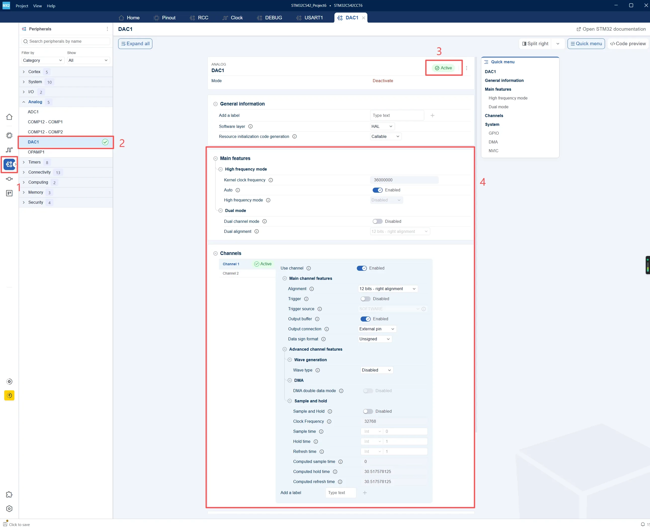
- Go to the Peripherals configuration page.
- Under the Analog category, select DAC1.
- Click Active to enable the DAC1 peripheral.
- Enable Channel 1 and configure it as 12 bits - right alignment. Disable Trigger, enable Output Buffer, set the output connection to External pin, select Unsigned as the data format, and keep Wave generation and Sample and Hold disabled.
In this experiment, the DAC data is updated directly by software, so no external trigger source is required. For fixed-voltage output applications, the Trigger can remain disabled, while the Output Buffer can be enabled to improve the output driving capability.
Continue with the System parameter configuration.
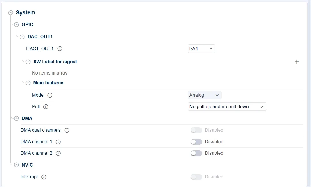
For DAC1 Channel 1, select PA4 as the external output pin for DAC1_OUT1. According to the STM32C5 datasheet, PA4 supports the DAC1_OUT1 analog output function.
Keep the GPIO parameters at their default analog-output settings:
- DAC1_OUT1: PA4
- Mode: Analog
- Pull: No pull-up and no pull-down
In this experiment, the DAC data register is updated directly by software to generate a fixed analog voltage. Since continuous data transfer is not required, DMA Channel 1 remains disabled. DAC interrupts are also not used, so NVIC Interrupt remains disabled.
Generate the Project
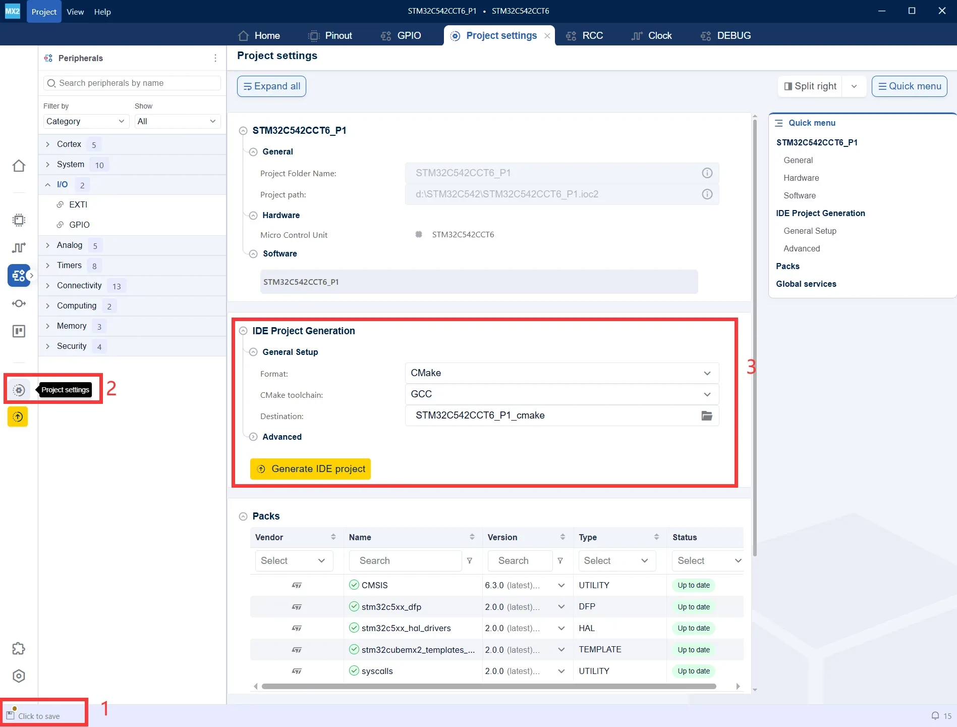
- After modifying the configuration, Click to save will appear in the lower-left corner. Save the current project configuration first.
- Click Project settings on the left to enter the project generation settings page.
- Under IDE Project Generation, select the project format and toolchain. In this example, choose CMake + GCC, and then click Generate IDE project to generate the project.
Import into STM32CubeIDE
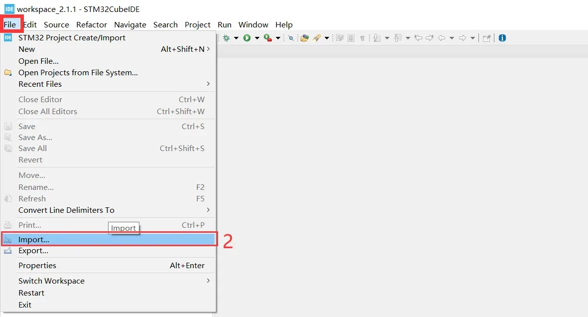
- Open STM32CubeIDE and click File on the menu bar.
- Select Import... to import the CMake project generated by STM32CubeMX2.
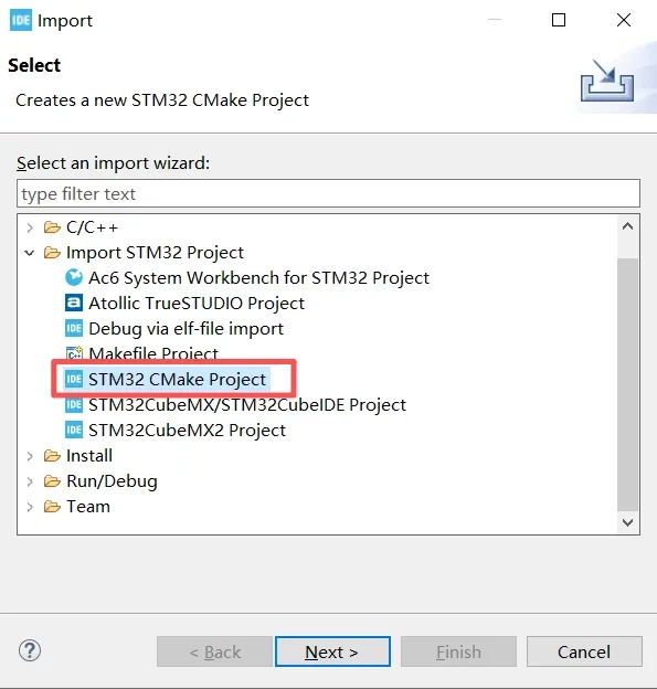
- In the Import window, expand Import STM32 Project.
- Select STM32 CMake Project.
- Click Next to proceed to the CMake project directory selection page.
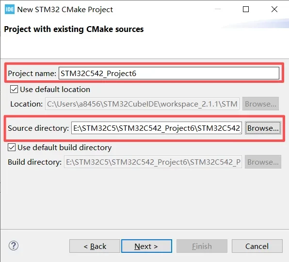
- Project name: Enter the project name to be displayed in STM32CubeIDE.
- Source directory: Select the CMake project directory generated by STM32CubeMX2.
- Click Next to continue the project import process.
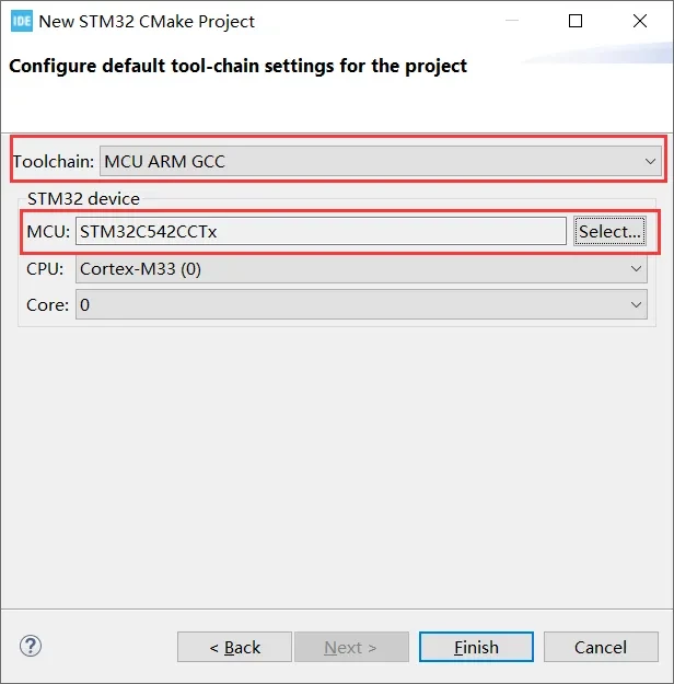
- Toolchain: Select MCU ARM GCC to compile the project using the ARM GCC toolchain.
- MCU: Confirm that the device is STM32C542CCTx, consistent with the MCU selected previously in STM32CubeMX2.
- CPU/Core: Confirm that the CPU is Cortex-M33 and the Core is 0.
- Click Finish to complete the CMake project import.
Set the Project Encoding
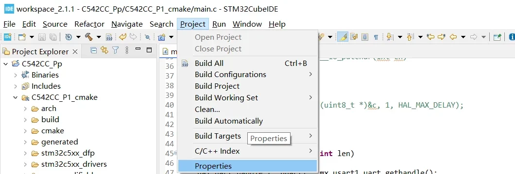
- In Project Explorer, select the current project.
- Click Project on the menu bar.
- Select Properties to open the project properties.
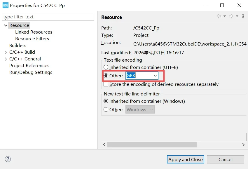
- In the project properties, select Resource.
- Under Text file encoding, select Other.
- Enter GBK as the encoding format.
- Click Apply and Close to save the settings.
Add Header Files
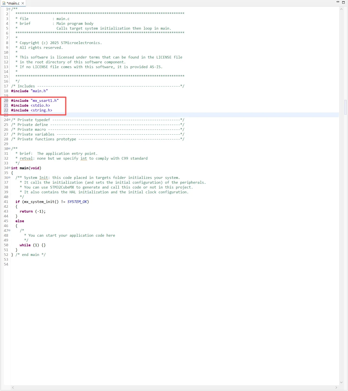
Add the following header files to main.c:
#include "mx_usart1.h"
#include <stdio.h>
#include <string.h>
printf Redirection
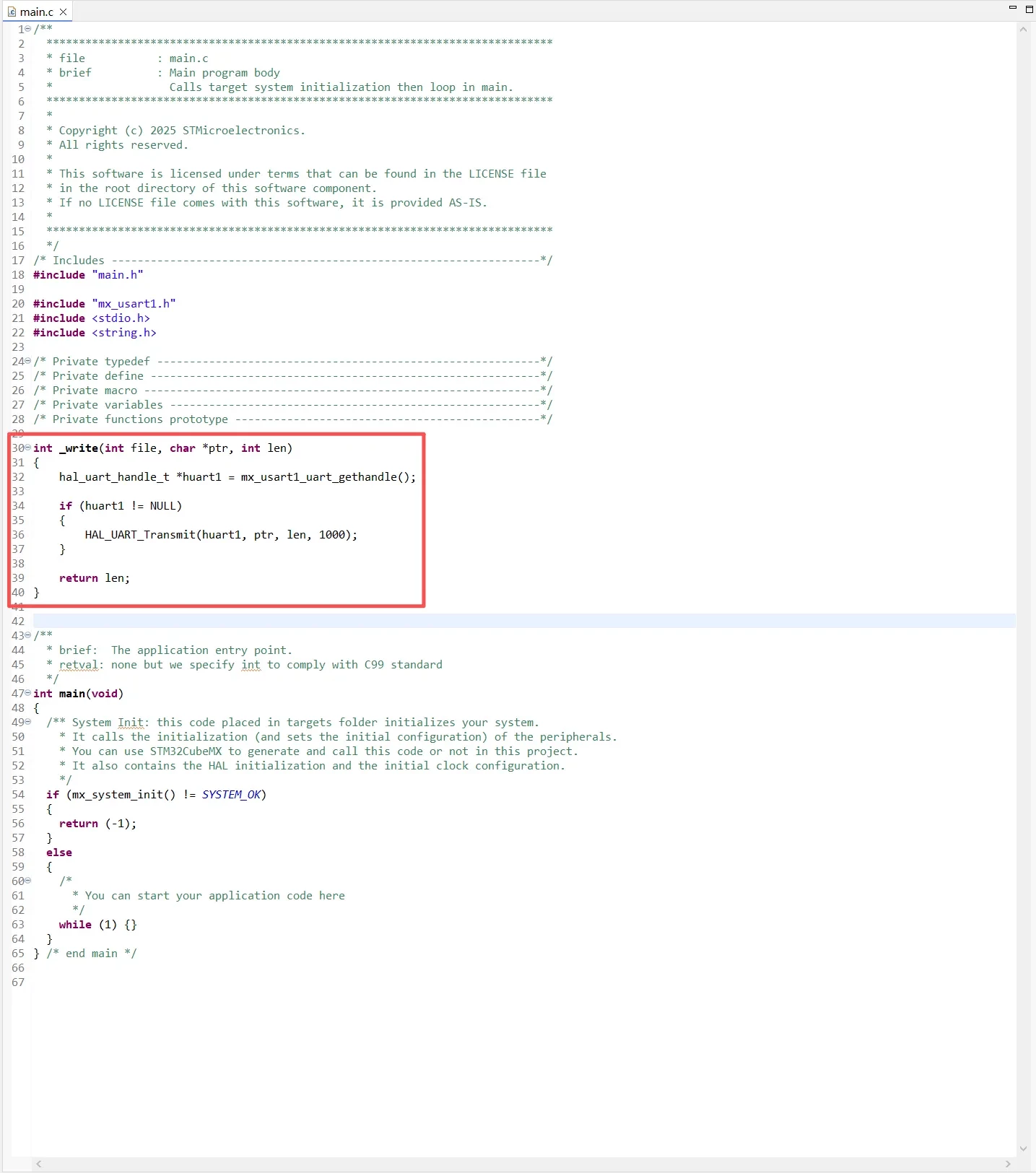
To redirect printf() output to USART1, the _write() function needs to be overridden. In a GCC project, printf() ultimately calls _write() to output characters. Therefore, by calling HAL_UART_Transmit() inside _write(), the formatted output from printf() can be sent through the UART.
int _write(int file, char *ptr, int len)
{
    hal_uart_handle_t *huart1 = mx_usart1_uart_gethandle();

    if (huart1 != NULL)
    {
        HAL_UART_Transmit(huart1, ptr, len, 1000);
    }

    return len;
}
Variable Definitions
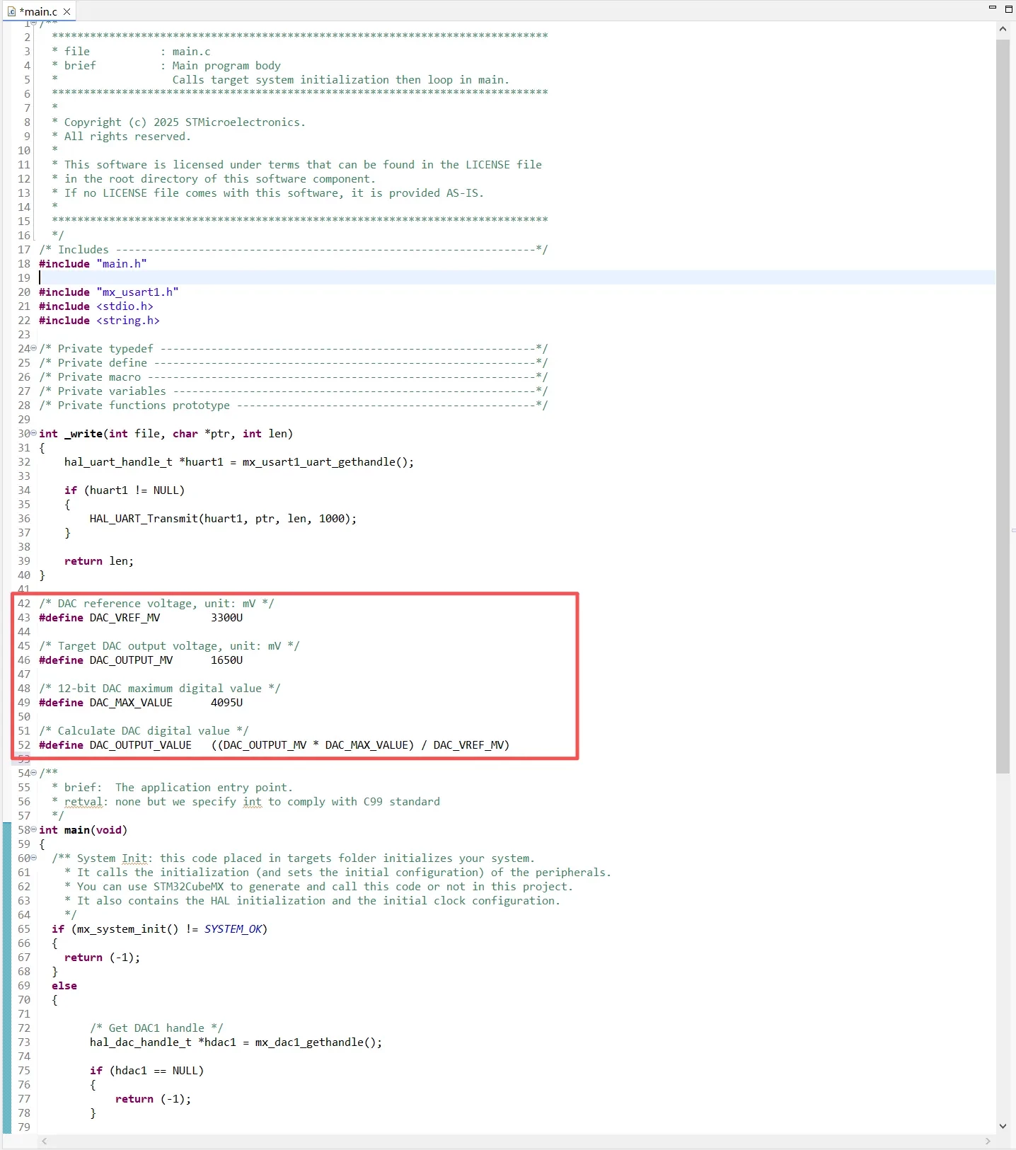
The STM32C542 DAC provides 12-bit resolution, with a digital input range of 0 to 4095. In this example, the DAC reference voltage VREF+ is assumed to be 3.3 V, and the target output voltage is set to 1.65 V. The program calculates the DAC digital value automatically according to the target voltage.
According to the STM32C5 reference manual, the DAC output voltage is determined by:
VOUT=(VREF+)×4095/DOR
where DOR is the DAC Data Output Register value.
For a target output voltage of 1.65 V:
DAC_OUTPUT_VALUE=1650×4095/3300≈2047
/* DAC reference voltage, unit: mV */
#define DAC_VREF_MV        3300U

/* Target DAC output voltage, unit: mV */
#define DAC_OUTPUT_MV      1650U

/* 12-bit DAC maximum digital value */
#define DAC_MAX_VALUE      4095U

/* Calculate DAC digital value */
#define DAC_OUTPUT_VALUE   ((DAC_OUTPUT_MV * DAC_MAX_VALUE) / DAC_VREF_MV)
Main Program
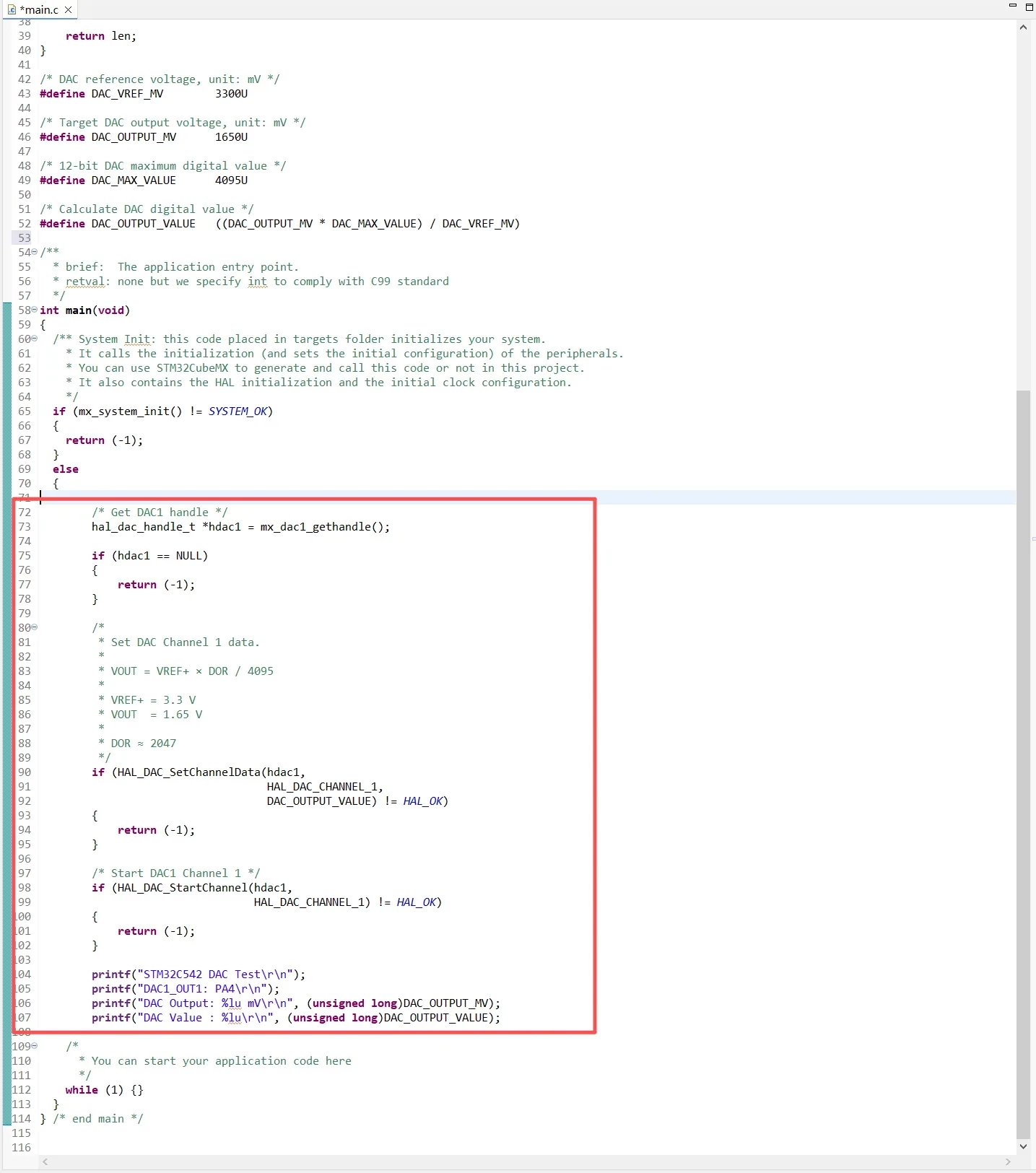
First, obtain the DAC1 handle using mx_dac1_gethandle() and check whether the handle is valid. Then call HAL_DAC_SetChannelData() to write the calculated DAC_OUTPUT_VALUE into the data holding register of DAC1 Channel 1.
According to the STM32C5 HAL2 usage sequence, the initial conversion data should be set using HAL_DAC_SetChannelData() before starting the DAC channel with HAL_DAC_StartChannel().
In this experiment, the reference voltage is set to 3.3 V and the target output voltage is 1.65 V. The corresponding 12-bit DAC digital value is approximately 2047:
DOR=1.65/3.3×4095≈2047
/* Get DAC1 handle */
hal_dac_handle_t *hdac1 = mx_dac1_gethandle();

if (hdac1 == NULL)
{
    return (-1);
}

/*
 * Set DAC Channel 1 data.
 *
 * VOUT = VREF+ × DOR / 4095
 *
 * VREF+ = 3.3 V
 * VOUT  = 1.65 V
 *
 * DOR ≈ 2047
 */
if (HAL_DAC_SetChannelData(hdac1,
                           HAL_DAC_CHANNEL_1,
                           DAC_OUTPUT_VALUE) != HAL_OK)
{
    return (-1);
}

/* Start DAC1 Channel 1 */
if (HAL_DAC_StartChannel(hdac1,
                         HAL_DAC_CHANNEL_1) != HAL_OK)
{
    return (-1);
}

printf("STM32C542 DAC Test\r\n");
printf("DAC1_OUT1: PA4\r\n");
printf("DAC Output: %lu mV\r\n", (unsigned long)DAC_OUTPUT_MV);
printf("DAC Value : %lu\r\n", (unsigned long)DAC_OUTPUT_VALUE);
Test Results
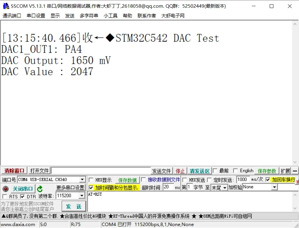
After running the program, the serial terminal shows that DAC1 uses PA4 (DAC1_OUT1) as the analog output pin. The target voltage is set to 1650 mV, corresponding to a 12-bit DAC digital value of 2047.
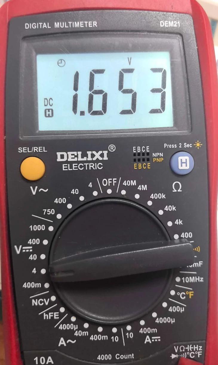
Using a multimeter to measure the voltage on the PA4 pin, the actual output voltage is approximately 1.653 V, which is very close to the theoretical value of 1.650 V. The error is about 3 mV, indicating that the STM32C542 DAC fixed-voltage output function is working correctly.