STM32C542 Development (5) — Timer Input Capture Configuration for Frequency Measurement
Overview
In the previous experiment, TIM1 was used to generate PWM output, and the PWM frequency and duty cycle were controlled by modifying the PSC, ARR, and CCR values.
Building on that experiment, this article uses the TIM15 input capture function to measure the PWM signal generated by TIM1, thereby detecting its frequency and duty cycle.
Hardware Preparation
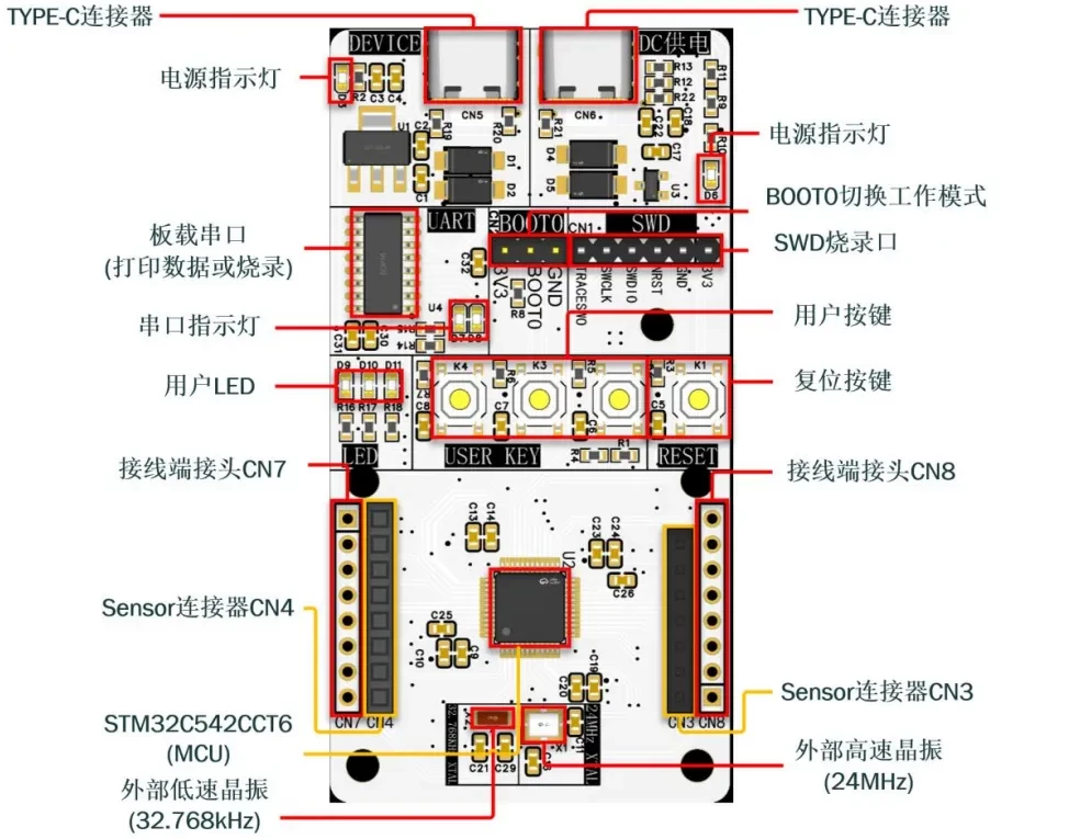
First, prepare a development board. In this tutorial, I use a custom-designed development board. If you are interested in obtaining one, you can apply for a sample.
The main controller is the STM32C542CCT6.
Reference Project
The reference project is available on GitHub:
https://github.com/CoreMaker-lab/STM32C542_SENSOR
UART Configuration
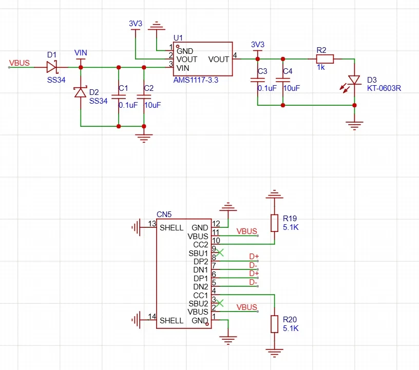
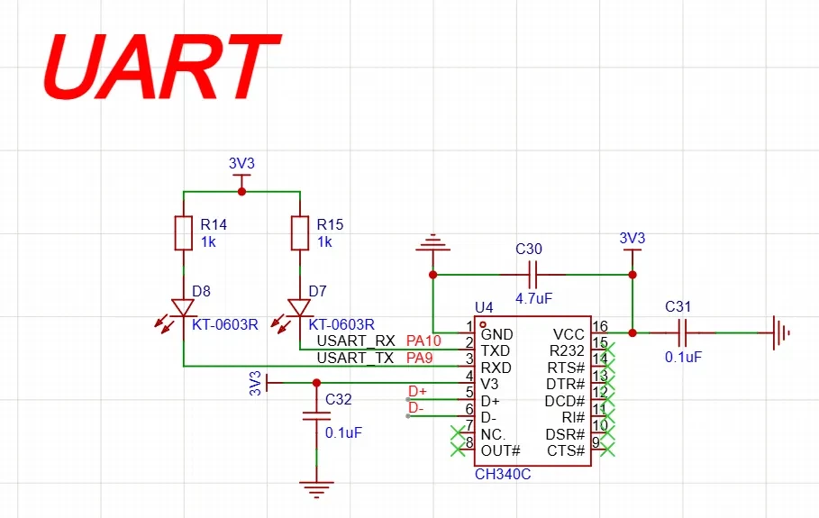
Refer to the schematic and note that PA9 and PA10 are connected to the UART interface on the development board.
-
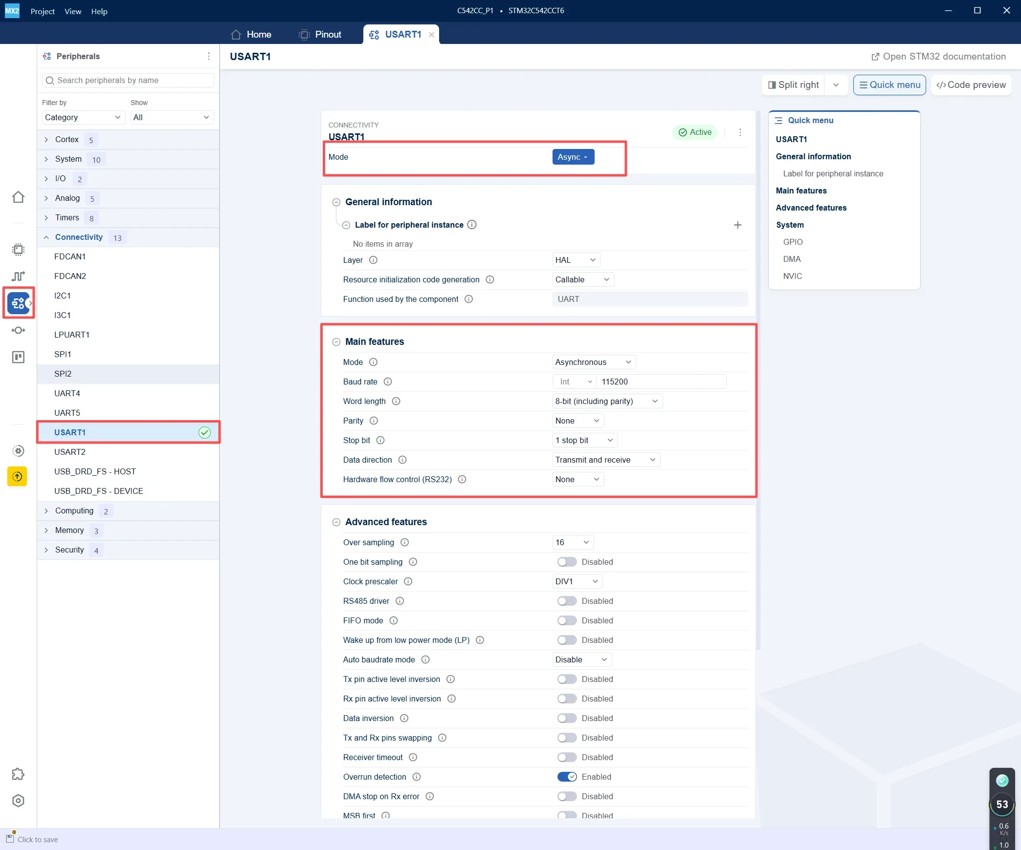
In the Peripherals panel, navigate to Connectivity → USART1.
-
Set Mode to Async to configure USART1 for asynchronous communication.
-
Verify that Function used by the component is displayed as UART, indicating that USART1 uses the UART HAL driver in asynchronous mode.
-
Configure the UART parameters as follows:
-
Baud Rate: 115200
-
Word Length: 8 Bits
-
Parity: None
-
Stop Bits: 1
-
Mode: TX and RX
-
-
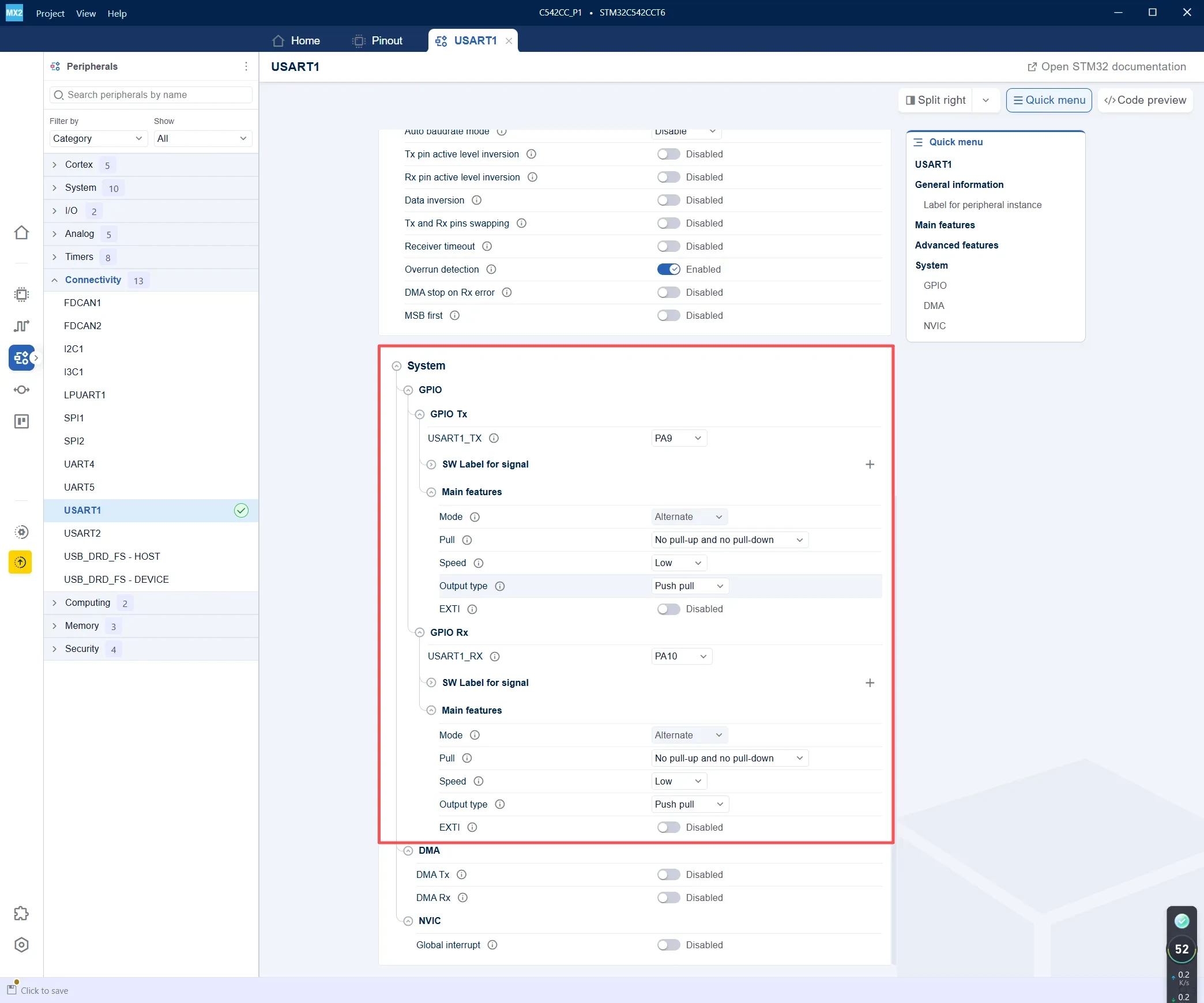
For GPIO Tx, assign USART1_TX to PA9.
-
For GPIO Rx, assign USART1_RX to PA10.
-
Configure both PA9 and PA10 in Alternate Function mode.
-
Set Pull to No pull-up and no pull-down, Output type to Push-pull, and Speed to Low.
TIM1 Basic Configuration
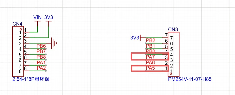
Use PA7 to capture the PWM signal output from PA5.
Before configuring the input capture function, first confirm the TIM15 input clock frequency. If the clock frequency is determined incorrectly, the calculated PWM frequency will also be inaccurate.
In this example:
TIM15 Clock = 144 MHz
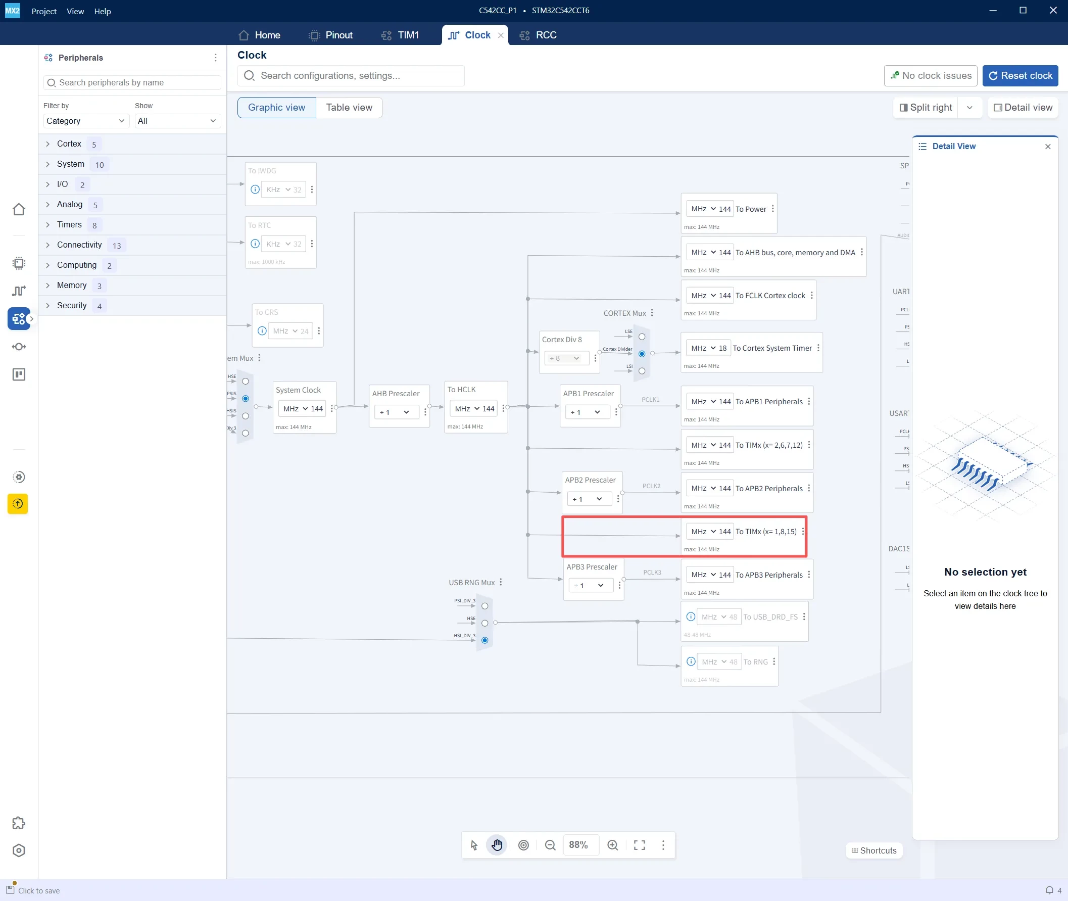
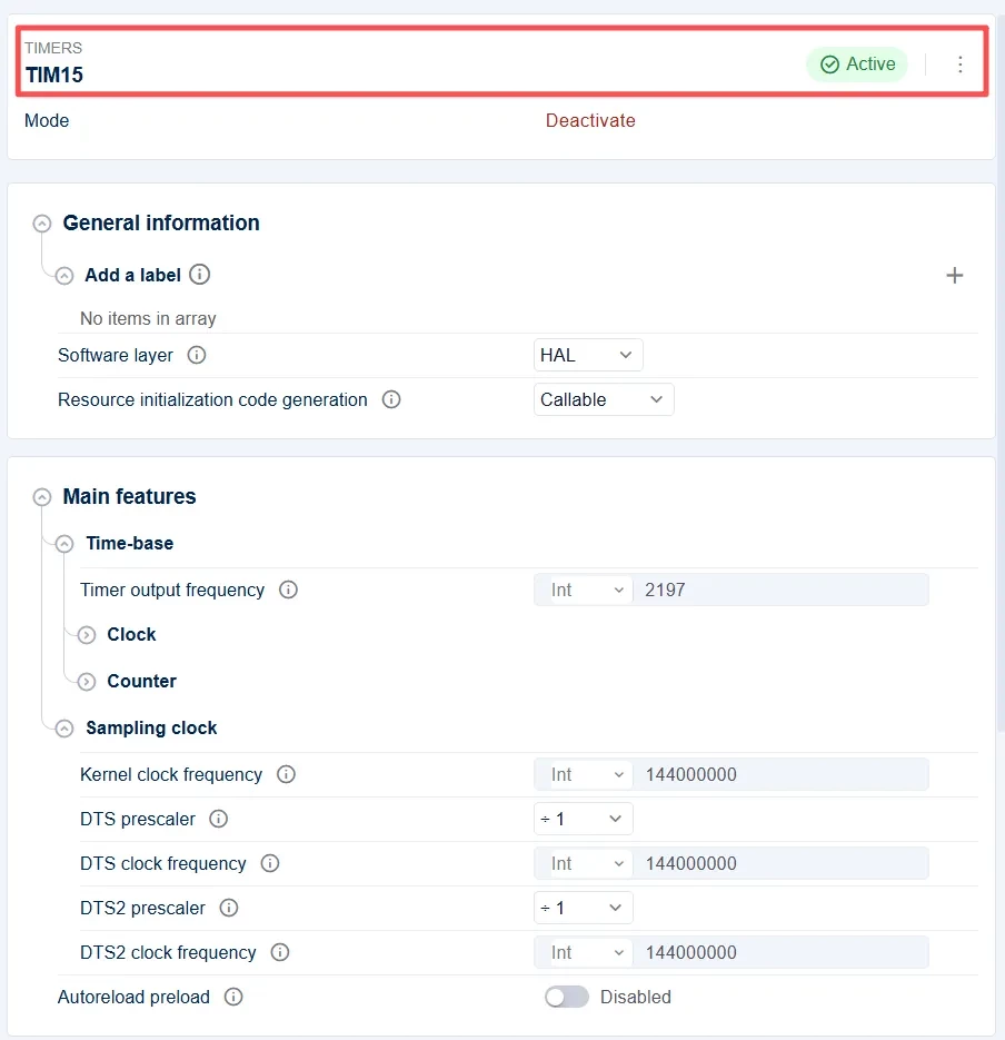
In STM32CubeMX2, navigate to Timers → TIM15 and enable the TIM15 peripheral.
In this example, the Prescaler and Counter period values are not fixed directly in STM32CubeMX2. Instead, they are configured in the code, making it easier to adjust the measurement resolution and measurement range later.
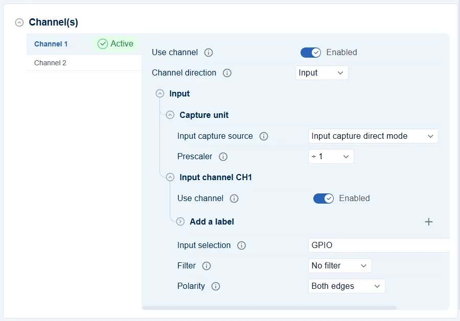
After completing the basic TIM15 configuration, the next step is to configure the TIM15_CH1 input capture channel.
In this example, TIM15_CH1 is used to capture the PWM signal generated by TIM1. The captured rising and falling edges are then used to calculate the PWM frequency and duty cycle.
Set Channel direction to Input, indicating that TIM15_CH1 is used as an input capture channel.
Set Input capture source to Input capture direct mode, meaning that the captured signal comes directly from the input pin associated with TIM15_CH1. In this example, TIM15_CH1 is mapped to PA7, so the external PWM signal must be connected to the PA7 pin.
Set Prescaler to ÷1. This means that every valid input edge triggers a capture event, with no division applied to the input capture events. This ensures that every PWM edge can be captured by TIM15.
Set Filter to No filter. In this experiment, the PWM signal generated by TIM1 is connected directly to TIM15_CH1 using a jumper wire, so the signal is relatively clean and no additional filtering is required. When measuring an external signal with more noise, the input filter can be enabled and adjusted as needed.
The most important configuration in this experiment is:
Polarity: Both edges
This configuration allows TIM15_CH1 to capture both the rising and falling edges of the input PWM signal. As a result, a single input capture channel can be used to measure both the PWM period and the high-level duration.
The measurement logic is as follows:
Rising edge      -> Save the start point of the PWM period
Falling edge     -> Save the end point of the high-level duration
Next rising edge -> Calculate the complete PWM period
Therefore:
Time from one rising edge to the next rising edge = PWM period
Time from the rising edge to the falling edge     = High-level duration
The PWM frequency can then be calculated as:
Frequency = TIM15_COUNTER_HZ / period
The duty cycle can be calculated as:
Duty Cycle = high / period × 100%
After TIM15_CH1 is configured to capture Both edges, every input capture interrupt enters HAL_TIM_InputCaptureCallback().
To determine whether the captured event is a rising edge or a falling edge, the program reads the current level of PA7:
pin_level = (GPIOA->IDR & GPIO_IDR_ID7);
If PA7 is currently at a high level, the captured event was a rising edge. If PA7 is currently at a low level, the captured event was a falling edge.
Using this method, the program can measure both the PWM frequency and duty cycle with a single input capture channel.
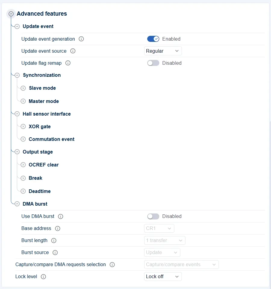
After configuring the TIM15_CH1 input capture channel, the TIM15 advanced-function settings should also be checked.
In this example, TIM15_CH1 is used only to capture and measure an external PWM signal, so most advanced-function settings can remain at their default values.
Keep Update event generation set to Enabled. This allows TIM15 to generate update events, which are normally associated with counter overflow, auto-reload, and other timer operations. Although this example mainly uses the input capture function, update event generation can remain enabled without any additional modification.
Set Update event source to Regular, which selects the standard update event source. For this PWM frequency measurement example, the default configuration can be retained.
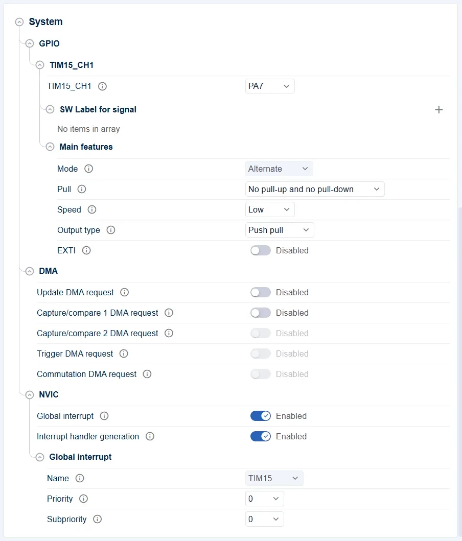
After configuring the TIM15_CH1 input capture channel, the corresponding GPIO and interrupt settings must also be checked.
In this example, TIM15_CH1 is used to capture the PWM signal generated by TIM1. Therefore, confirm that TIM15_CH1 is correctly mapped to PA7 and that the TIM15 interrupt is enabled.
Because this example uses input capture interrupts, whenever PA7 detects a rising or falling edge of the PWM signal, TIM15 generates an input capture event and enters the HAL_TIM_InputCaptureCallback() callback function.
If the TIM15 Global interrupt is not enabled, the input capture callback function will not be executed even if TIM15_CH1 is configured correctly. As a result, the program will be unable to calculate the PWM frequency and duty cycle.
In this example, TIM15_CH1 is configured to capture Both edges, so both rising and falling edges trigger input capture interrupts.
Inside the callback function, the program reads the captured counter value and checks the current logic level of PA7 to determine whether the captured event was a rising edge or a falling edge. It then calculates the PWM period, high-level duration, frequency, and duty cycle.
Set the Project Encoding
-
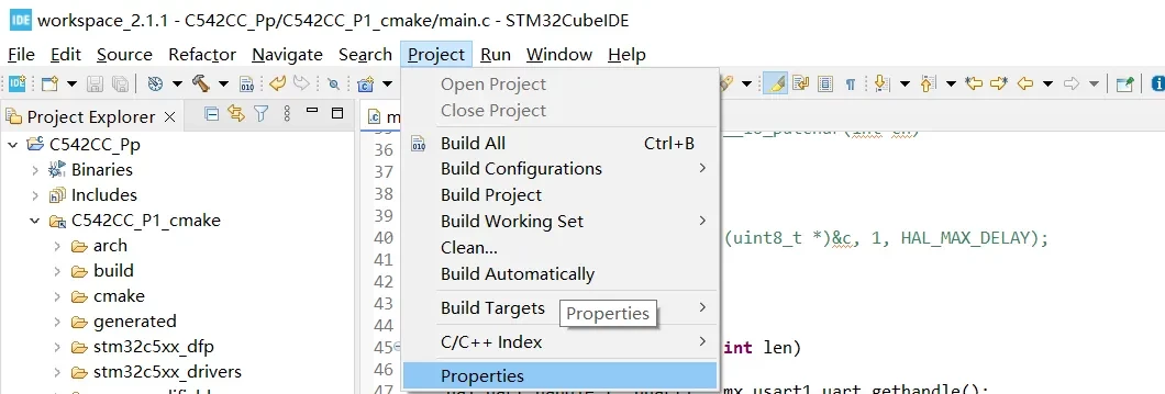
In the Project Explorer, select the current project.
-
Click Project from the menu bar.
-
Select Properties to open the project properties dialog.
-
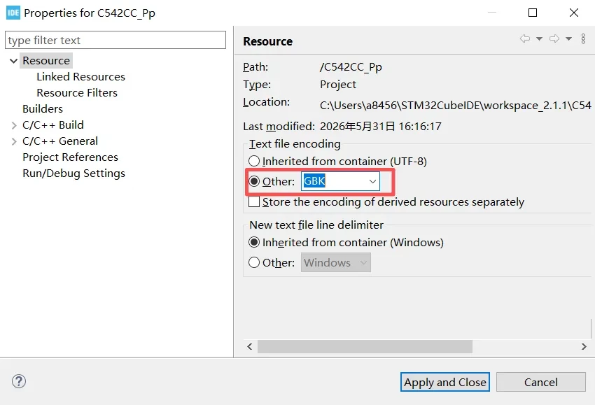
In the Project Properties dialog, select Resource.
-
Under Text file encoding, choose Other.
-
Set the encoding to GBK.
-
Click Apply and Close to save the settings.
Initial Configuration
Modify the initial configuration as follows.
/**
  * brief:  The application entry point.
  * retval: none but we specify int to comply with C99 standard
  */
int main(void)
{
  /** System Init: this code placed in targets folder initializes your system.
    * It calls the initialization (and sets the initial configuration) of the peripherals.
    * You can use STM32CubeMX to generate and call this code or not in this project.
    * It also contains the HAL initialization and the initial clock configuration.
    */
  if (mx_system_init() != SYSTEM_OK)
  {
    return (-1);
  }
  else
  {
    /*
      * You can start your application code here
      */
	    /*
	     * TIM1_CH1 -> PB8
	     * TIM1_CH3 -> PA5
	     *
	     * 当前配置:
	     * TIM1_CLK = 144 MHz
	     * ARR = 9999
	     */

	    /*
	     * 设置 PWM 频率为 1Hz
	     *
	     * PWM频率 = 144MHz / ((PSC + 1) * (ARR + 1))
	     * ARR = 9999
	     * 当 freq = 1Hz 时,PSC = 14399
	     */
	    if (TIM1_SetFrequency(1) != HAL_OK)
	    {
	        printf("TIM1_SetFrequency failed\r\n");
	    }

	    /*
	     * 设置多通道占空比
	     *
	     * CH1 = 25%
	     * CH3 = 75%
	     */
	    if (TIM1_SetChannelDuty(HAL_TIM_CHANNEL_1, TIM1_PWM_ARR, 25) != HAL_OK)
	    {
	        printf("TIM1 CH1 duty set failed\r\n");
	    }

	    if (TIM1_SetChannelDuty(HAL_TIM_CHANNEL_3, TIM1_PWM_ARR, 75) != HAL_OK)
	    {
	        printf("TIM1 CH3 duty set failed\r\n");
	    }

	    /*
	     * 启动 TIM1 CH1 和 CH3 PWM 输出
	     */
	    if (TIM1_PWM_Start_CH1_CH3() != HAL_OK)
	    {
	        printf("TIM1 PWM start failed\r\n");
	    }

        printf("TIM1 PWM: 1000Hz, CH1=25%%, CH3=75%%\r\n");

        /*
         * 设置 TIM1 PWM 频率为 1000Hz
         *
         * TIM1_CLK = 144MHz
         * ARR = 999
         * PSC = 143
         *
         * PWM频率 = 144MHz / ((143 + 1) * (999 + 1))
         *         = 1000Hz
         */
        TIM1_SetFrequency(1000);

        /*
         * CH1 输出 25% 占空比
         * CH3 输出 75% 占空比
         */
        TIM1_SetChannelDuty(HAL_TIM_CHANNEL_1, TIM1_PWM_ARR, 25);
        TIM1_SetChannelDuty(HAL_TIM_CHANNEL_3, TIM1_PWM_ARR, 75);

	    HAL_Delay(5000);
	    while (1)
	    {

	    }
	  }
} /* end main */
Adding Header Files
Add the required header files to main.c.
#include "mx_usart1.h"
#include <string.h>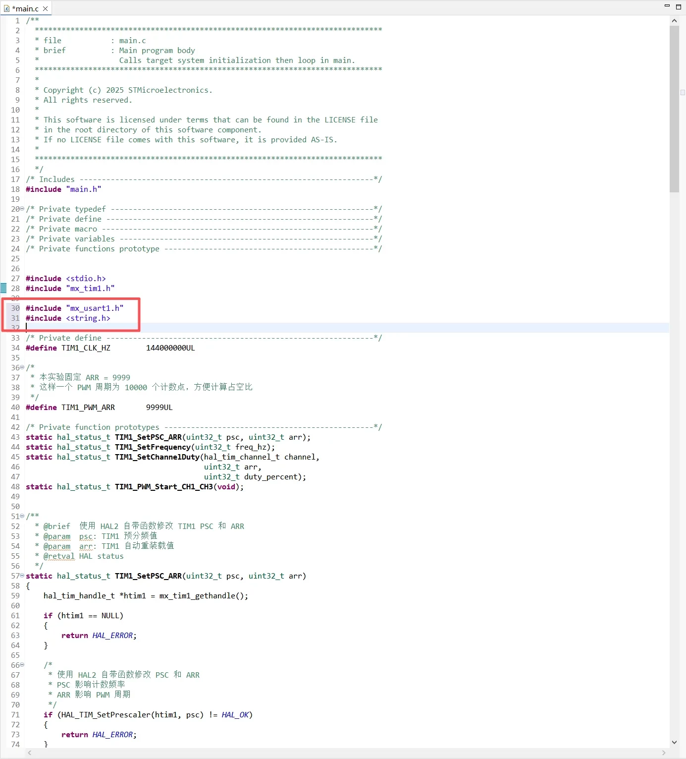
Retargeting printf()
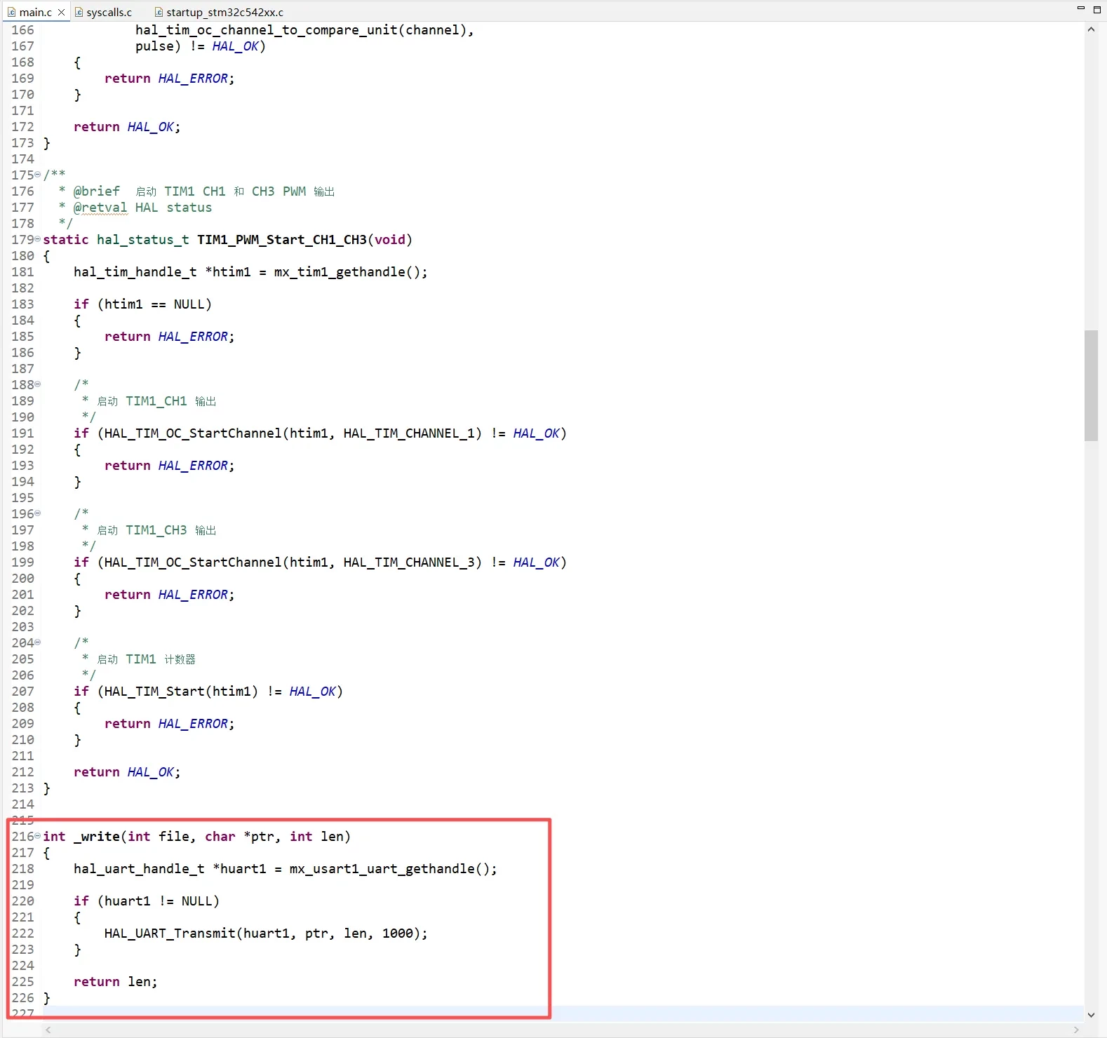
To redirect printf() output to USART1, the _write() function must be overridden.
In a GCC project, printf() calls _write() internally to output characters. Therefore, by calling HAL_UART_Transmit() inside _write(), the content generated by printf() can be transmitted through the serial port.
int _write(int file, char *ptr, int len)
{
    hal_uart_handle_t *huart1 = mx_usart1_uart_gethandle();

    if (huart1 != NULL)
    {
        HAL_UART_Transmit(huart1, ptr, len, 1000);
    }

    return len;
}
TIM15 Counter Frequency Configuration
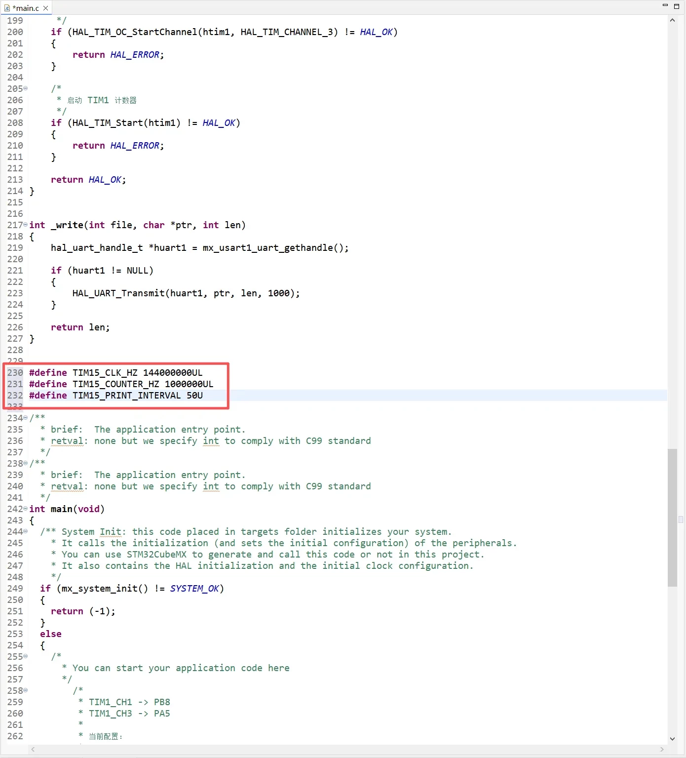
TIM15_CLK_HZ defines the TIM15 input clock frequency, which is 144 MHz in this example.
TIM15_COUNTER_HZ defines the desired TIM15 counter frequency, which is set to 1 MHz.
TIM15_PRINT_INTERVAL specifies that the measurement result is printed once every 50 measurements.
#define TIM15_CLK_HZ         144000000UL
#define TIM15_COUNTER_HZ       1000000UL
#define TIM15_PRINT_INTERVAL         50U
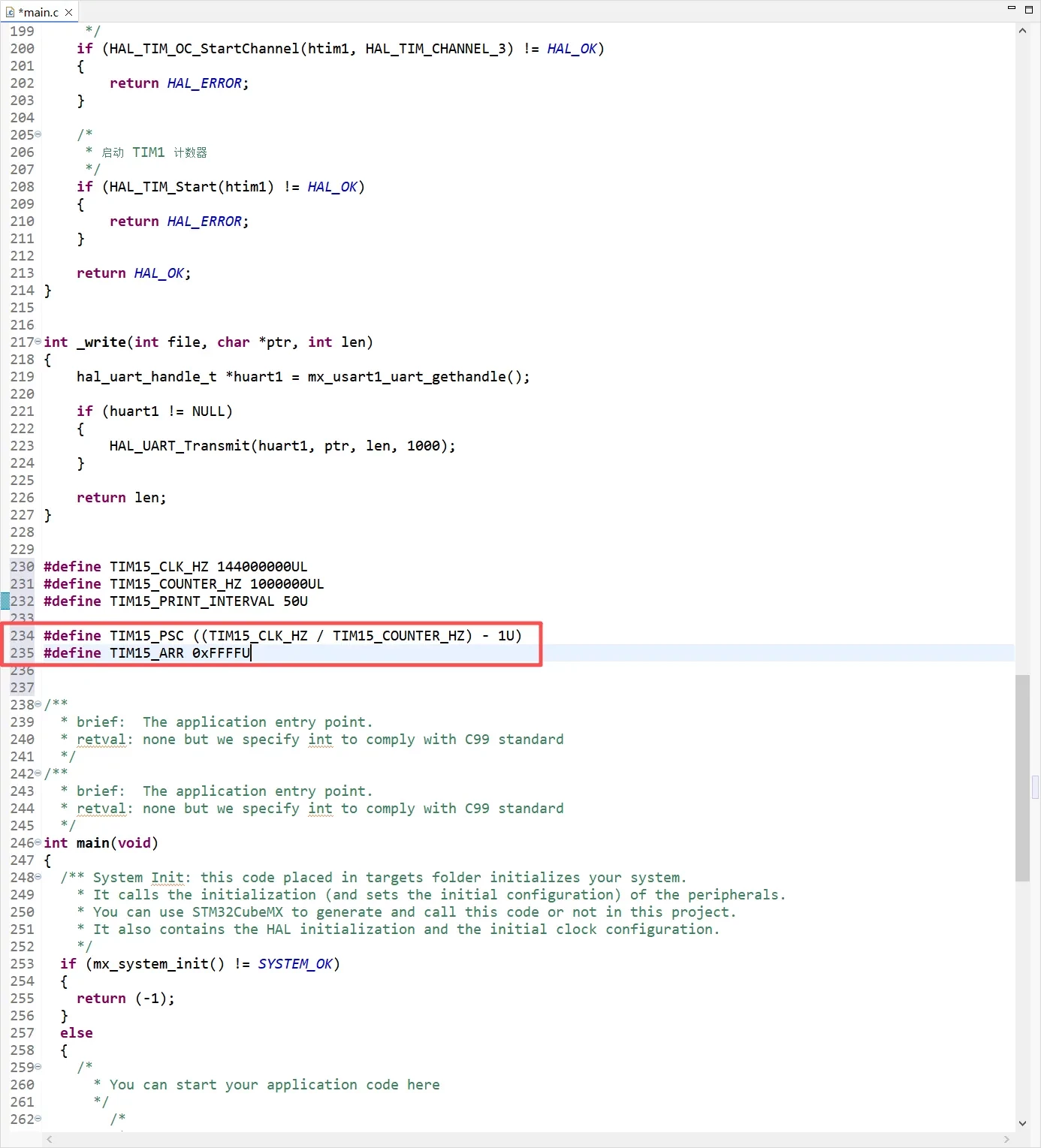
To set the TIM15 counter frequency to 1 MHz, configure the prescaler as follows:
#define TIM15_PSC ((TIM15_CLK_HZ / TIM15_COUNTER_HZ) - 1U)
#define TIM15_ARR 0xFFFFU
The calculation is:
TIM15 Counter Frequency = TIM15_CLK_HZ / (PSC + 1)
Given:
TIM15_CLK_HZ     = 144 MHz
TIM15_COUNTER_HZ = 1 MHz
the prescaler value is:
PSC = 144,000,000 / 1,000,000 - 1
    = 143
Therefore, when TIM15_PSC is set to 143, the TIM15 counter frequency is 1 MHz, which means:
1 counter tick = 1 us
This makes PWM measurement straightforward. For example, if the input PWM frequency is 1000 Hz, its period is 1 ms, or 1000 us. Therefore, the captured counter difference between two consecutive rising edges should theoretically be approximately 1000.
Capture Variable Description
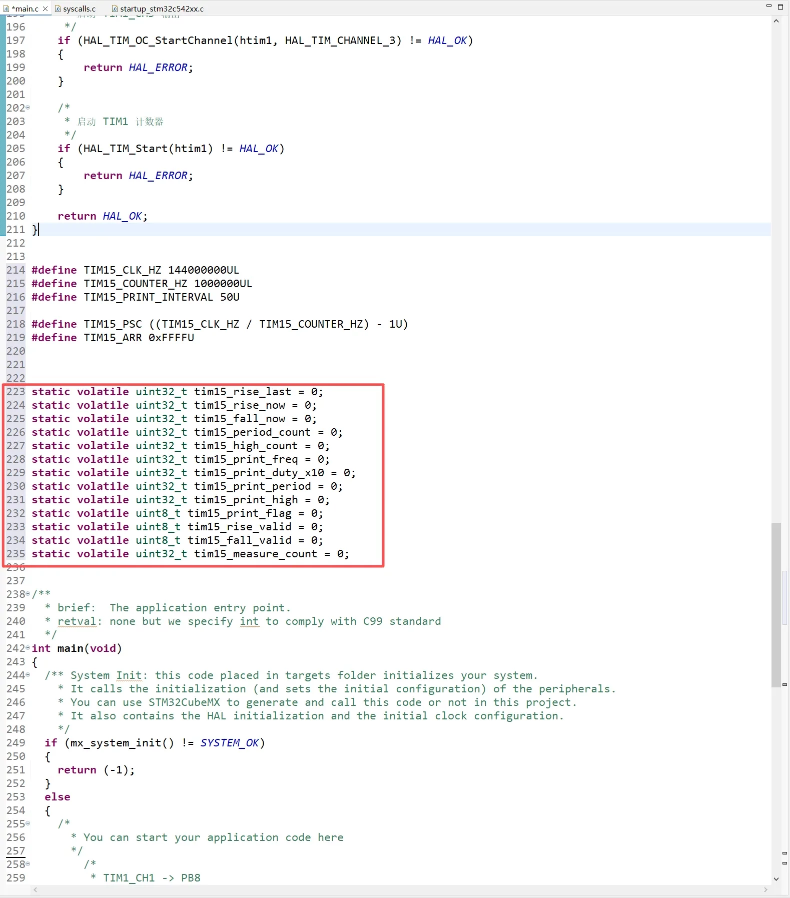
The code defines a group of variables used to store the captured rising-edge values, falling-edge values, and measurement results.
The purpose of each variable is described below:
-
tim15_rise_last: Captured value of the previous rising edge -
tim15_rise_now: Captured value of the current rising edge -
tim15_fall_now: Captured value of the current falling edge -
tim15_period_count: PWM period count value -
tim15_high_count: PWM high-level count value -
tim15_print_freq: Frequency value to be printed -
tim15_print_duty_x10: Duty-cycle value to be printed, multiplied by 10 -
tim15_print_period: Period count value to be printed -
tim15_print_high: High-level count value to be printed -
tim15_print_flag: Print flag -
tim15_rise_valid: Rising-edge capture valid flag -
tim15_fall_valid: Falling-edge capture valid flag -
tim15_measure_count: Measurement counter
static volatile uint32_t tim15_rise_last = 0;
static volatile uint32_t tim15_rise_now = 0;
static volatile uint32_t tim15_fall_now = 0;
static volatile uint32_t tim15_period_count = 0;
static volatile uint32_t tim15_high_count = 0;
static volatile uint32_t tim15_print_freq = 0;
static volatile uint32_t tim15_print_duty_x10 = 0;
static volatile uint32_t tim15_print_period = 0;
static volatile uint32_t tim15_print_high = 0;
static volatile uint8_t tim15_print_flag = 0;
static volatile uint8_t tim15_rise_valid = 0;
static volatile uint8_t tim15_fall_valid = 0;
static volatile uint32_t tim15_measure_count = 0;
Handling Counter Overflow
Because TIM15 is a 16-bit timer and the Counter period is set to 0xFFFF, the counter counts from 0 to 65535 and then rolls over to 0.
Therefore, counter overflow must be considered when calculating the difference between two captured values.
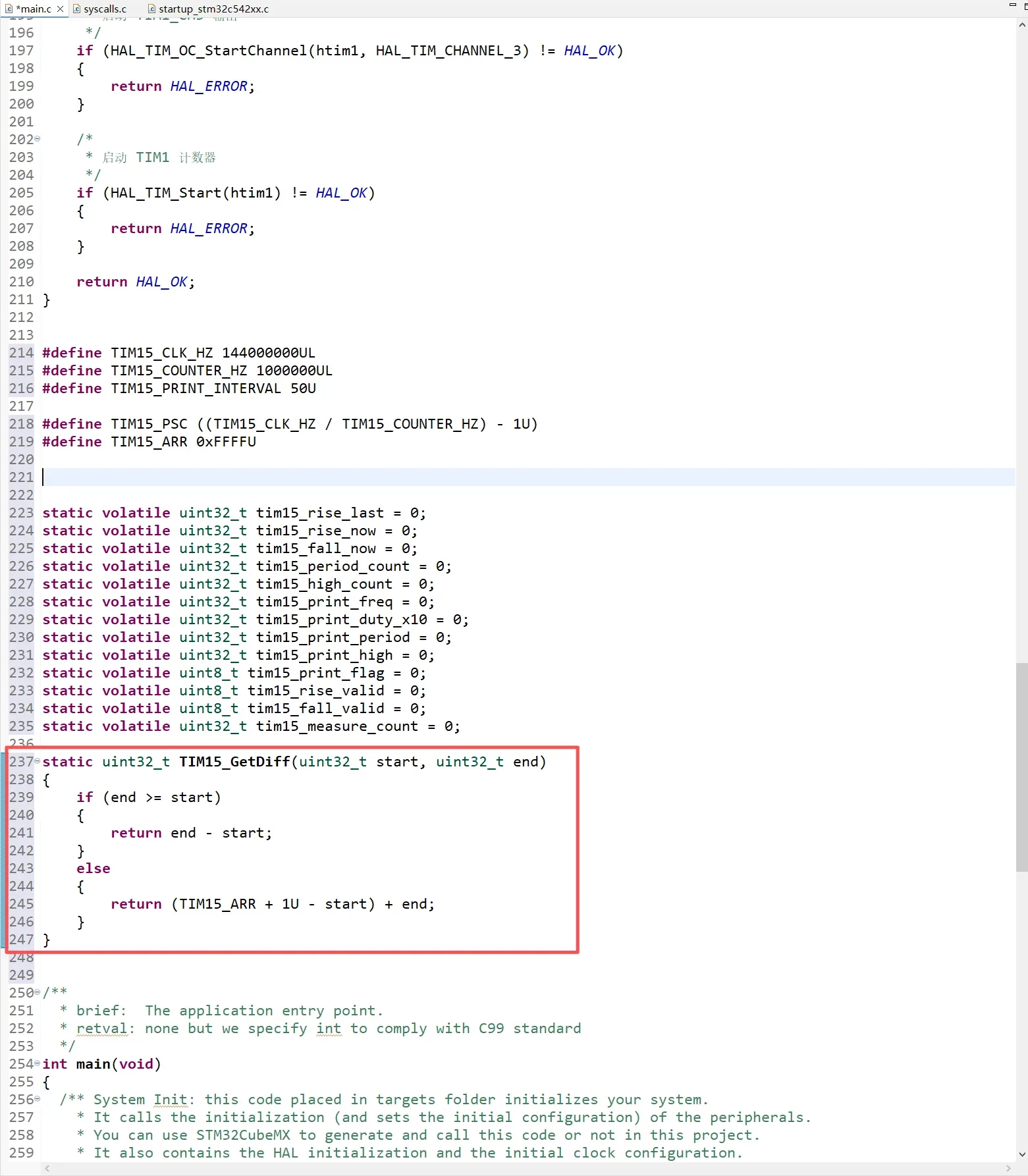
The code defines a TIM15_GetDiff() function to handle both normal counting and overflow conditions:
static uint32_t TIM15_GetDiff(uint32_t start, uint32_t end)
{
    if (end >= start)
    {
        return end - start;
    }
    else
    {
        return (TIM15_ARR + 1U - start) + end;
    }
}
When end is greater than or equal to start, the difference can be calculated directly.
When end is less than start, the counter has overflowed. In this case, the remaining counts before overflow and the counts after rollover are added together to obtain the correct difference.
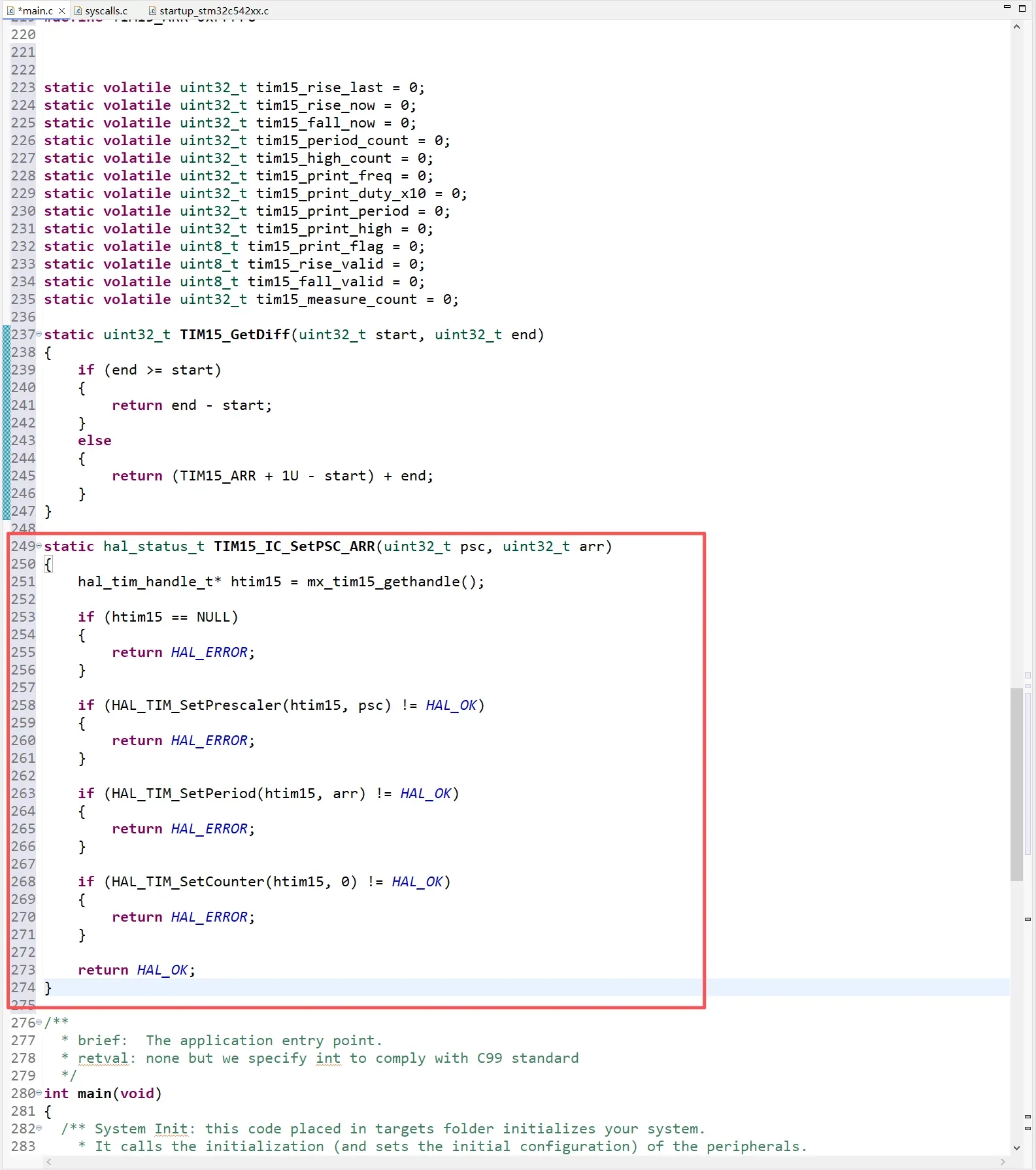
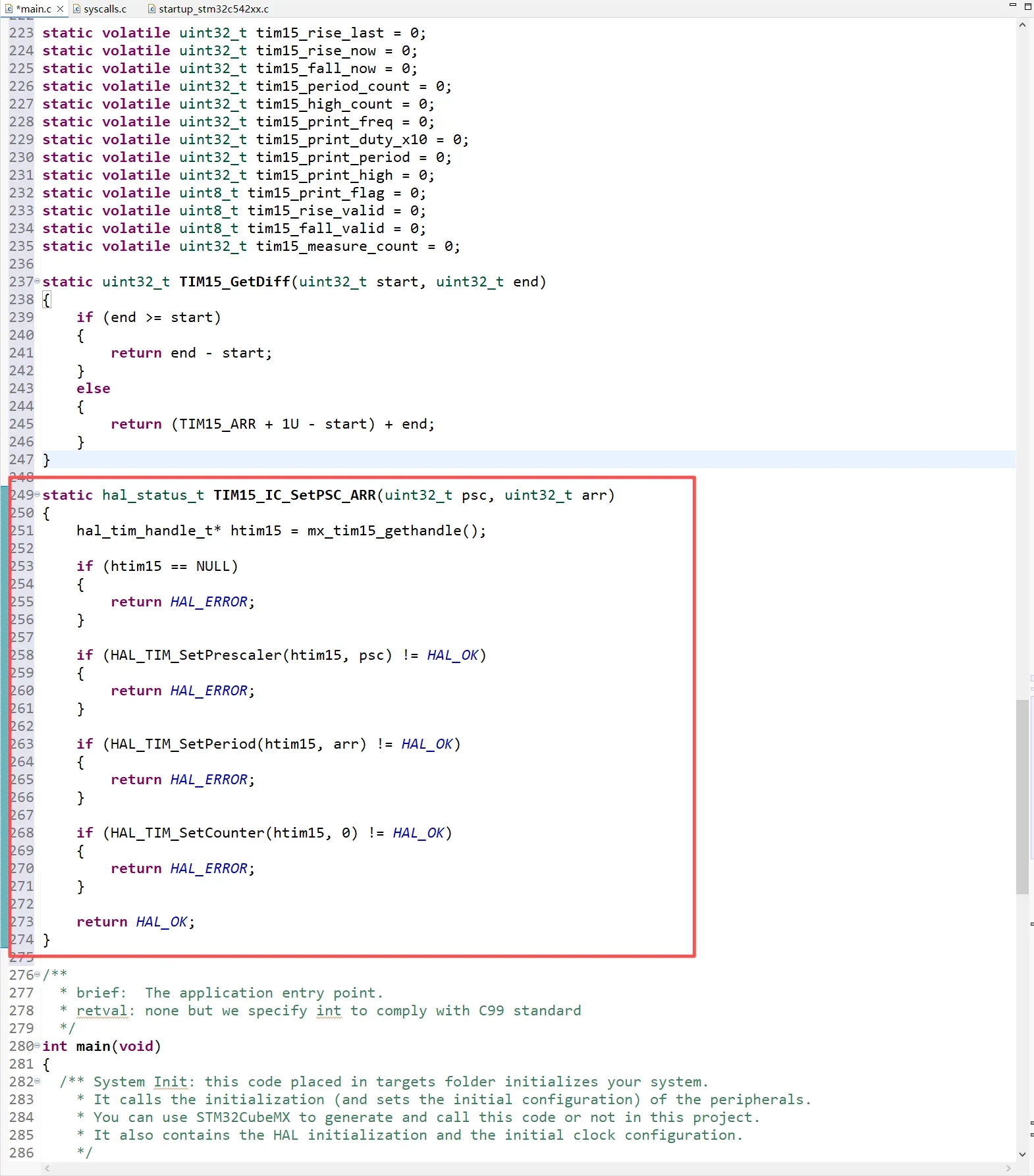
In this example, the TIM15 Prescaler and Counter period values are not fixed in STM32CubeMX2. Instead, they are configured dynamically in the code using HAL2 functions.
This function performs three main operations:
-
Uses
HAL_TIM_SetPrescaler()to configureTIM15_PSC. -
Uses
HAL_TIM_SetPeriod()to configureTIM15_ARR. -
Uses
HAL_TIM_SetCounter()to reset the TIM15 counter to zero.
static hal_status_t TIM15_IC_SetPSC_ARR(uint32_t psc, uint32_t arr)
{
    hal_tim_handle_t* htim15 = mx_tim15_gethandle();

    if (htim15 == NULL)
    {
        return HAL_ERROR;
    }

    if (HAL_TIM_SetPrescaler(htim15, psc) != HAL_OK)
    {
        return HAL_ERROR;
    }

    if (HAL_TIM_SetPeriod(htim15, arr) != HAL_OK)
    {
        return HAL_ERROR;
    }

    if (HAL_TIM_SetCounter(htim15, 0) != HAL_OK)
    {
        return HAL_ERROR;
    }

    return HAL_OK;
}
Starting the Input Capture Interrupt
After completing the basic TIM15 configuration, the TIM15_CH1 input capture interrupt must be started.
-
HAL_TIM_IC_StartChannel_IT()starts the TIM15_CH1 input capture interrupt. -
HAL_TIM_Start()starts the TIM15 counter.
static hal_status_t TIM15_IC_Start(void)
{
    hal_tim_handle_t* htim15 = mx_tim15_gethandle();

    if (htim15 == NULL)
    {
        return HAL_ERROR;
    }

    /*
     * Start the TIM15_CH1 input capture interrupt.
     */
    if (HAL_TIM_IC_StartChannel_IT(htim15, HAL_TIM_CHANNEL_1) != HAL_OK)
    {
        return HAL_ERROR;
    }

    /*
     * Start the TIM15 counter.
     */
    if (HAL_TIM_Start(htim15) != HAL_OK)
    {
        return HAL_ERROR;
    }

    return HAL_OK;
}
Input Capture Callback Function
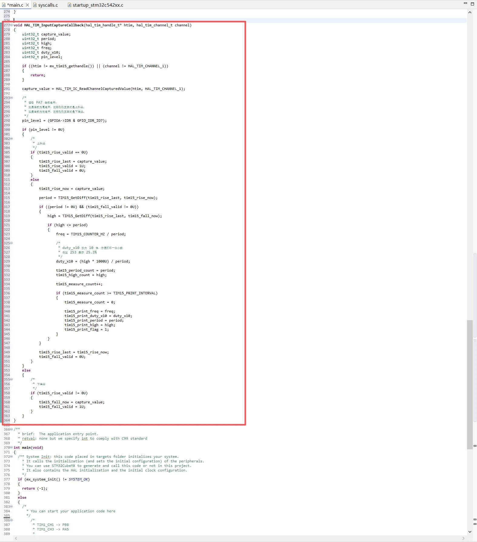
In STM32CubeMX2, TIM15_CH1 is configured to capture Both edges, meaning that both rising and falling edges trigger an input capture interrupt.
Because the same callback function responds to both edge types, the program reads the current logic level of PA7 to determine which edge was captured:
pin_level = (GPIOA->IDR & GPIO_IDR_ID7);
The logic is as follows:
-
If PA7 is currently high, a rising edge has just occurred.
-
If PA7 is currently low, a falling edge has just occurred.
void HAL_TIM_InputCaptureCallback(hal_tim_handle_t* htim, hal_tim_channel_t channel)
{
    uint32_t capture_value;
    uint32_t period;
    uint32_t high;
    uint32_t freq;
    uint32_t duty_x10;
    uint32_t pin_level;

    if ((htim != mx_tim15_gethandle()) || (channel != HAL_TIM_CHANNEL_1))
    {
        return;
    }

    capture_value = HAL_TIM_IC_ReadChannelCapturedValue(htim, HAL_TIM_CHANNEL_1);

    /*
     * 读取 PA7 当前电平:
     * 如果当前为高电平,说明刚刚发生的是上升沿;
     * 如果当前为低电平,说明刚刚发生的是下降沿。
     */
    pin_level = (GPIOA->IDR & GPIO_IDR_ID7);

    if (pin_level != 0U)
    {
        /*
         * 上升沿
         */
        if (tim15_rise_valid == 0U)
        {
            tim15_rise_last = capture_value;
            tim15_rise_valid = 1U;
            tim15_fall_valid = 0U;
        }
        else
        {
            tim15_rise_now = capture_value;

            period = TIM15_GetDiff(tim15_rise_last, tim15_rise_now);

            if ((period != 0U) && (tim15_fall_valid != 0U))
            {
                high = TIM15_GetDiff(tim15_rise_last, tim15_fall_now);

                if (high <= period)
                {
                    freq = TIM15_COUNTER_HZ / period;

                    /*
                     * duty_x10 放大 10 倍,方便打印一位小数
                     * 例如 253 表示 25.3%
                     */
                    duty_x10 = (high * 1000U) / period;

                    tim15_period_count = period;
                    tim15_high_count = high;

                    tim15_measure_count++;

                    if (tim15_measure_count >= TIM15_PRINT_INTERVAL)
                    {
                        tim15_measure_count = 0;

                        tim15_print_freq = freq;
                        tim15_print_duty_x10 = duty_x10;
                        tim15_print_period = period;
                        tim15_print_high = high;
                        tim15_print_flag = 1;
                    }
                }
            }

            tim15_rise_last = tim15_rise_now;
            tim15_fall_valid = 0U;
        }
    }
    else
    {
        /*
         * 下降沿
         */
        if (tim15_rise_valid != 0U)
        {
            tim15_fall_now = capture_value;
            tim15_fall_valid = 1U;
        }
    }
}
Adding TIM15 Initialization and Startup
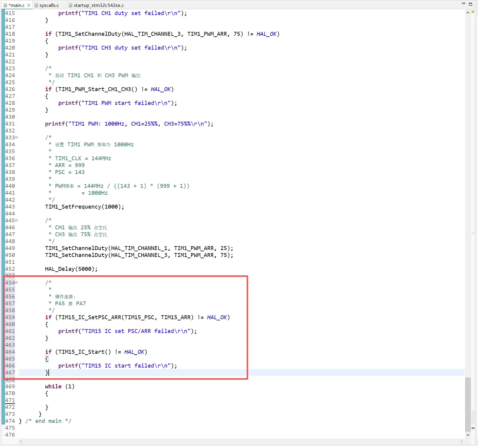
In the main() function, add the TIM15 initialization and startup code after starting the TIM1 PWM output:
/*
 *
 * 硬件连接:
 * PA5 接 PA7
 */
if (TIM15_IC_SetPSC_ARR(TIM15_PSC, TIM15_ARR) != HAL_OK)
{
    printf("TIM15 IC set PSC/ARR failed\r\n");
}

if (TIM15_IC_Start() != HAL_OK)
{
    printf("TIM15 IC start failed\r\n");
}
Main Loop
Inside while (1), the program checks whether tim15_print_flag has been set.
while (1)
{
    if (tim15_print_flag)
    {
        uint32_t freq;
        uint32_t duty_x10;
        uint32_t period;
        uint32_t high;

        __disable_irq();

        tim15_print_flag = 0;
        freq = tim15_print_freq;
        duty_x10 = tim15_print_duty_x10;
        period = tim15_print_period;
        high = tim15_print_high;

        __enable_irq();

        printf("TIM15 measured: freq=%lu Hz, duty=%lu.%lu%%, period=%lu, high=%lu\r\n",
               freq,
               duty_x10 / 10U,
               duty_x10 % 10U,
               period,
               high);
    }
}
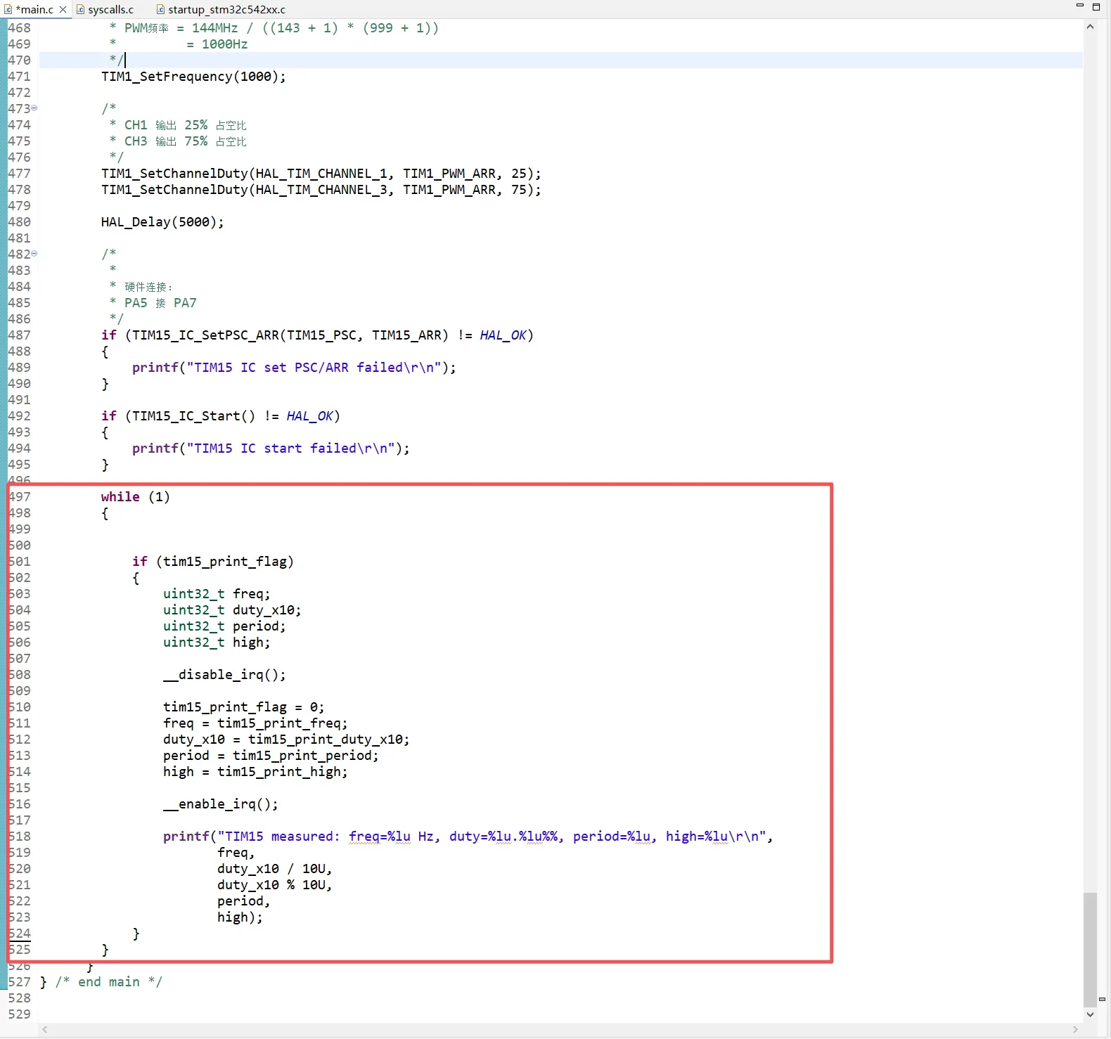
Interrupts are temporarily disabled to prevent the capture interrupt from updating these variables while the main loop is reading them. Otherwise, the program could read a mixture of old and new measurement data.
After all values have been copied to local variables, interrupts are re-enabled and the results are printed through the serial port:
-
freq: Measured PWM frequency -
duty: Measured PWM duty cycle -
period: Counter value corresponding to one complete PWM period -
high: Counter value corresponding to the high-level duration
For an input signal of 1000 Hz with a 25% duty cycle, the expected output is approximately:
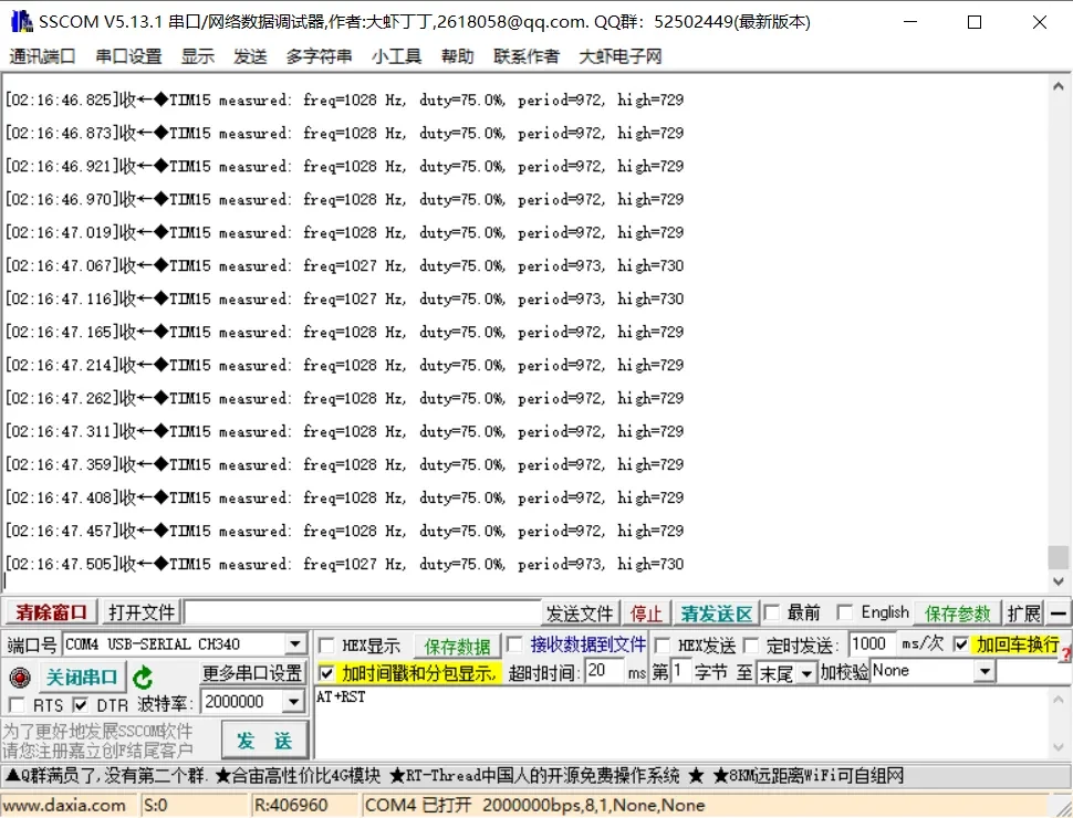
TIM15 measured: freq=1000 Hz, duty=25.0%, period=1000, high=250
For an input signal of 1000 Hz with a 75% duty cycle, the expected output is approximately:
TIM15 measured: freq=1000 Hz, duty=75.0%, period=1000, high=750
Demonstration Results
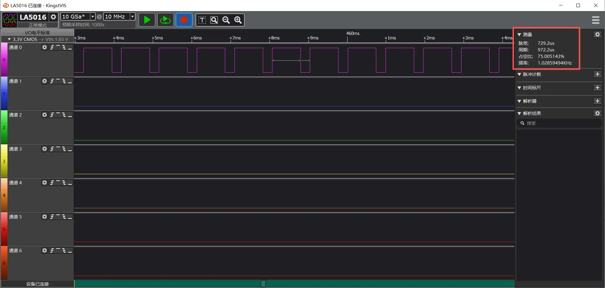
The frequency measured by both the logic analyzer and the serial output is approximately 1025 Hz, with a duty cycle of approximately 75%.