STM32C542 Development (4) — PWM Output and Frequency/Duty Cycle Adjustment
Overview
Timers are among the most commonly used peripherals in an MCU. They can be used for periodic timing, PWM generation, input capture, output compare, motor control, and many other applications.
This tutorial is based on the STM32C542CCT6. It uses STM32CubeMX2 to configure TIM1 and demonstrates how to modify the prescaler (PSC) and auto-reload register (ARR) using the built-in HAL2 functions, thereby changing the timer output frequency. It also introduces the basic usage of multi-channel PWM output.
Hardware Preparation
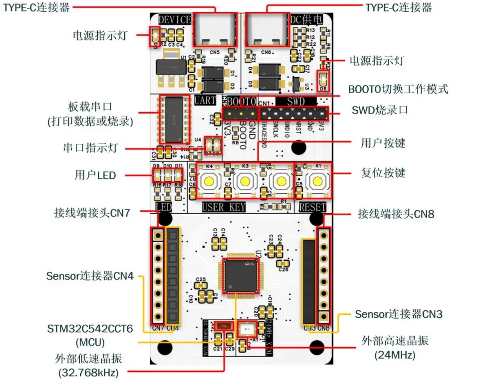
First, prepare a development board. In this tutorial, I use a custom-designed development board. If you are interested in obtaining one, you can apply for a sample.
The main controller is the STM32C542CCT6.
Reference Project
The reference project is available on GitHub:
https://github.com/CoreMaker-lab/STM32C542_SENSOR
Creating a Project with STM32CubeMX2
Use STM32CubeMX2 to generate the example project. The MCU used in this tutorial is the STM32C542CCT6.
-
Open STM32CubeMX2 and go to the Home page.
-
Click MCU to create a new project based on a specific device.
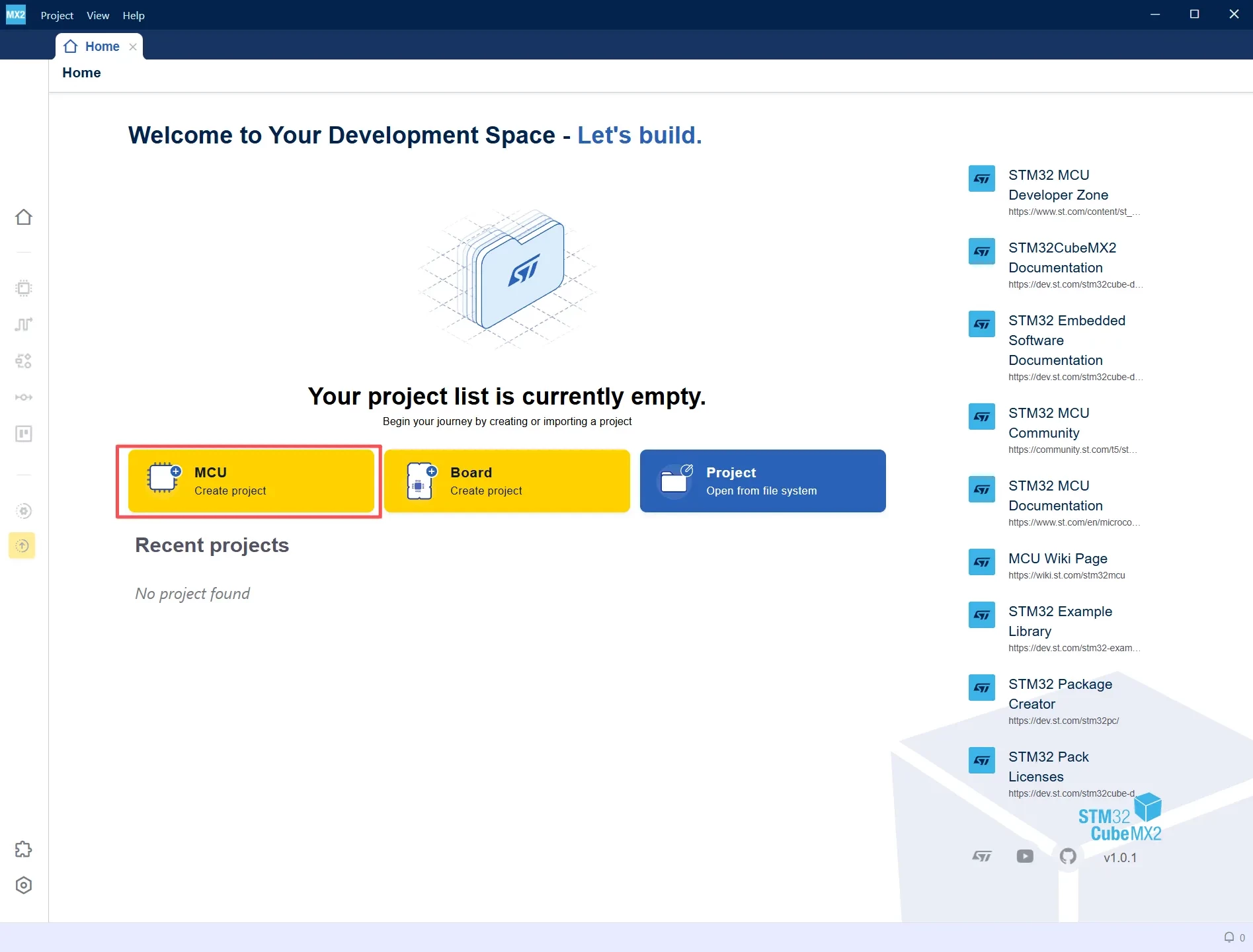
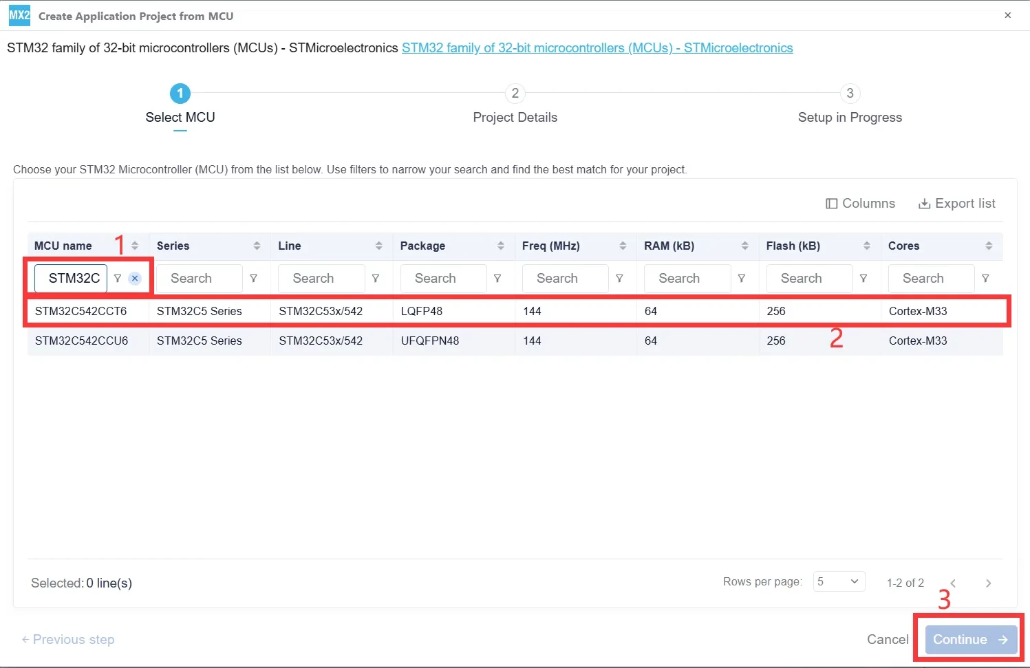
Enter STM32C542CCT6 in the MCU name field. Select the corresponding STM32C5 device from the list, then click Continue to proceed to the project configuration page.
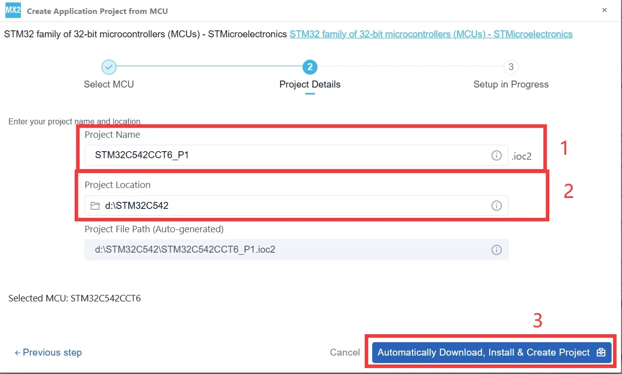
After entering the project name and selecting the project directory, click Automatically Download, Install & Create Project. STM32CubeMX2 will automatically download the required software packages and generate the project.
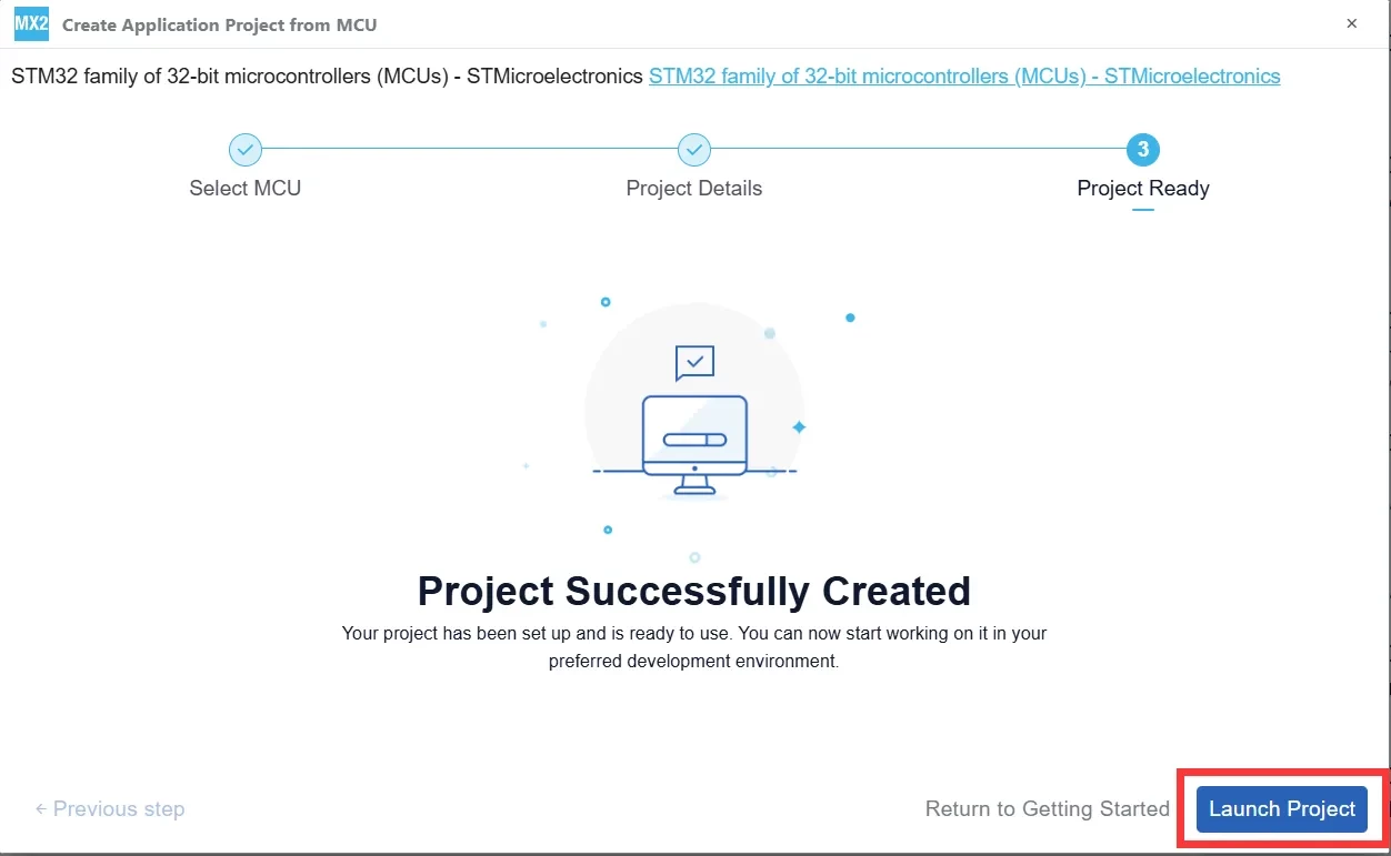
After STM32CubeMX2 displays the Project Successfully Created message, click Launch Project in the lower-right corner to open the project configuration interface.
Clock Configuration
-
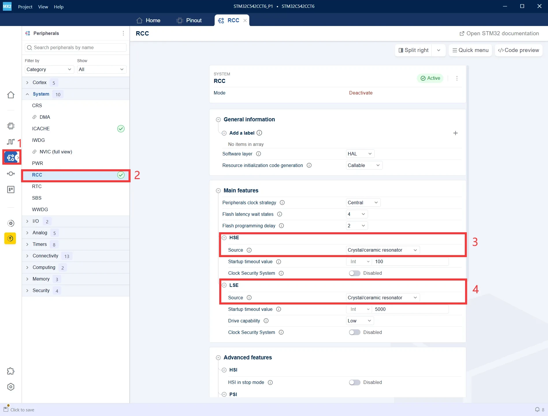
In the left-side panel, click Peripherals to open the peripheral configuration page.
-
Under the System category, select RCC to configure the system clock source.
-
Set HSE Source to Crystal/Ceramic Resonator to enable the external high-speed oscillator (HSE).
-
Set LSE Source to Crystal/Ceramic Resonator to enable the external low-speed oscillator (LSE).
-
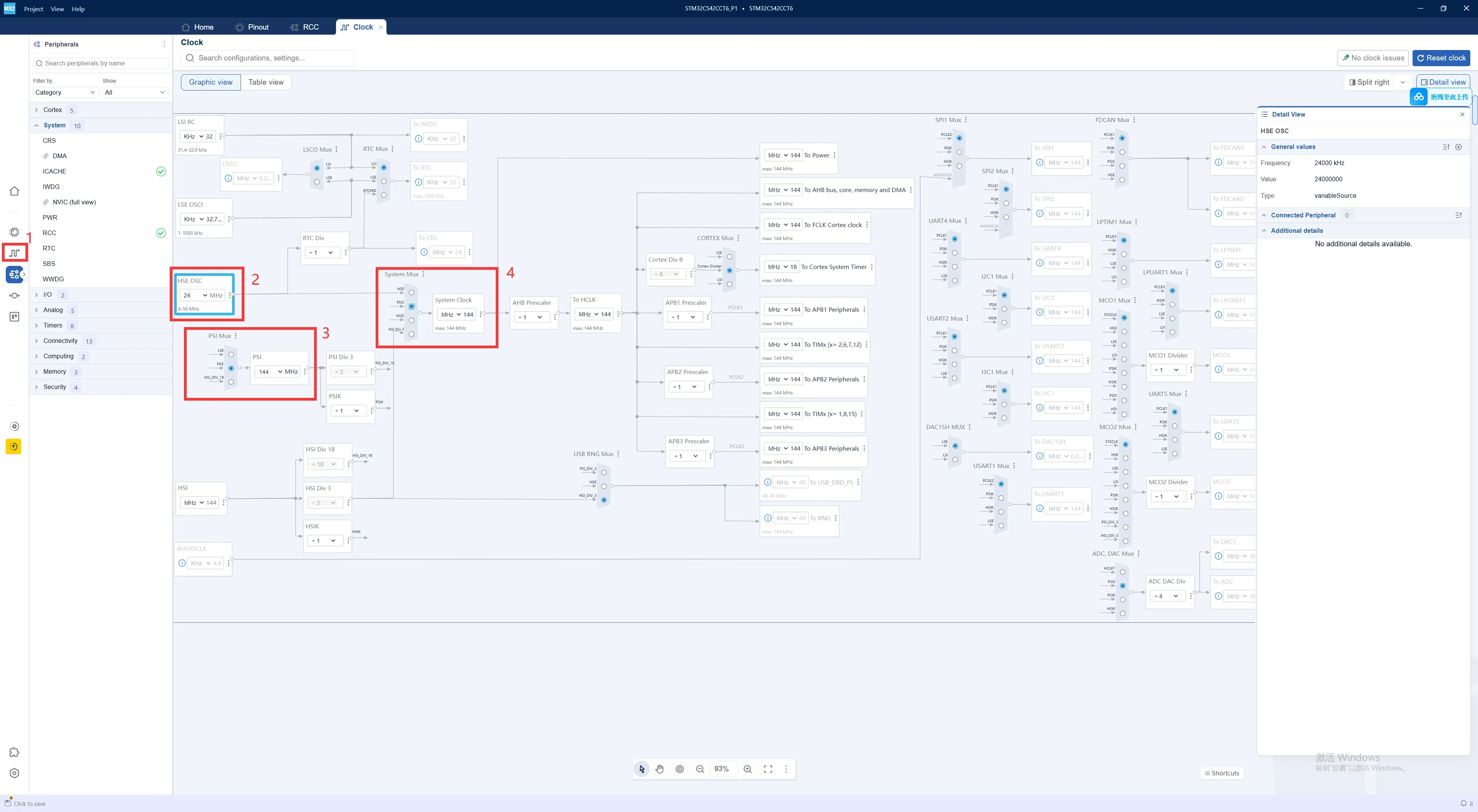
Click the Clock icon in the left-side panel to open the Clock Configuration page.
-
Set HSE OSC to 24 MHz to match the external high-speed crystal frequency.
-
Configure PSI Mux / PLL to select the PLL clock source and generate the desired system clock frequency.
-
Set System Mux to use the PLL as the system clock source. In this example, the system clock is configured to 144 MHz.
DEBUG Configuration
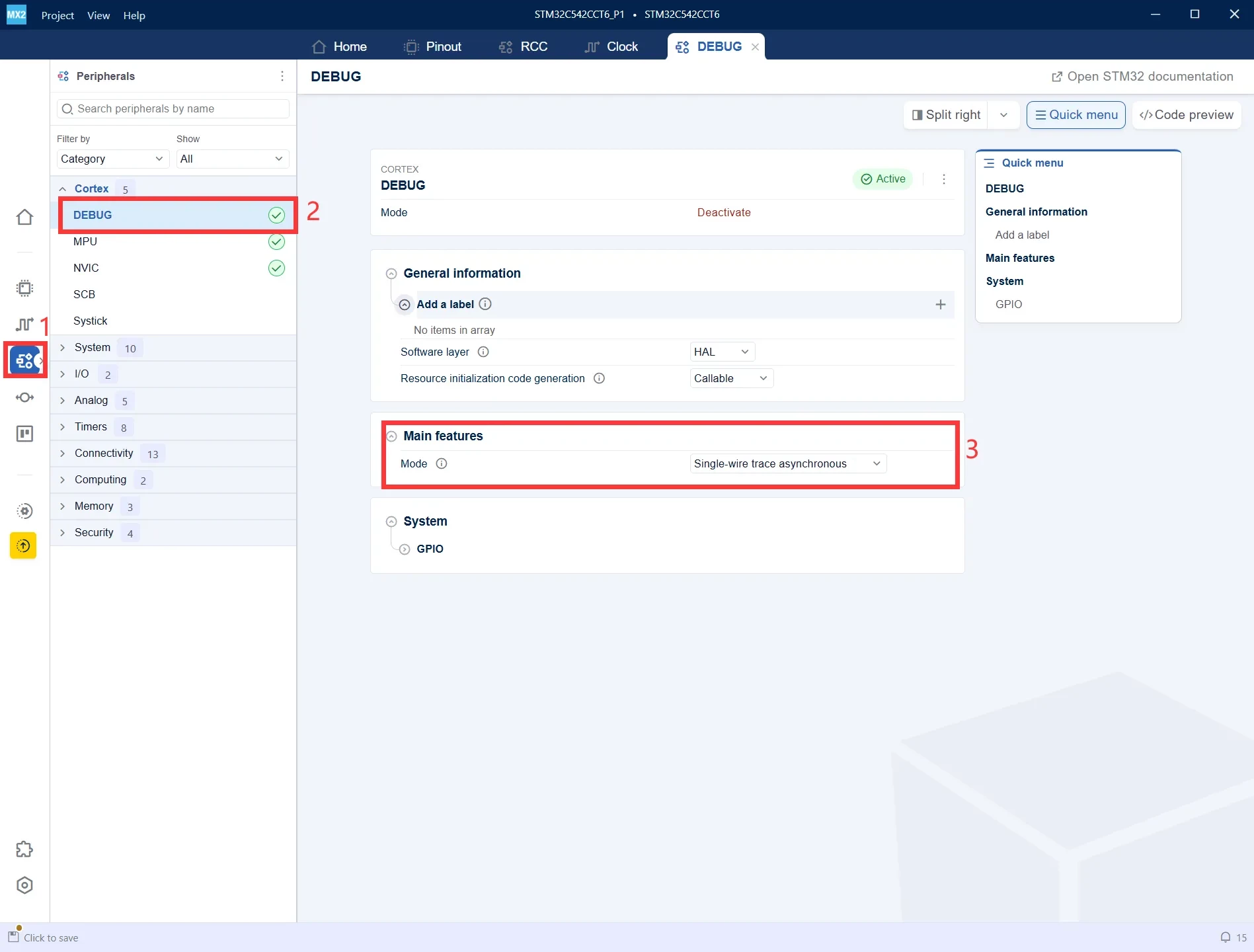
In the Peripherals panel, navigate to Cortex → DEBUG, then set Mode to Single-wire trace asynchronous. This enables program downloading, on-chip debugging, and Trace debugging in subsequent development.
TIM1 Basic Configuration
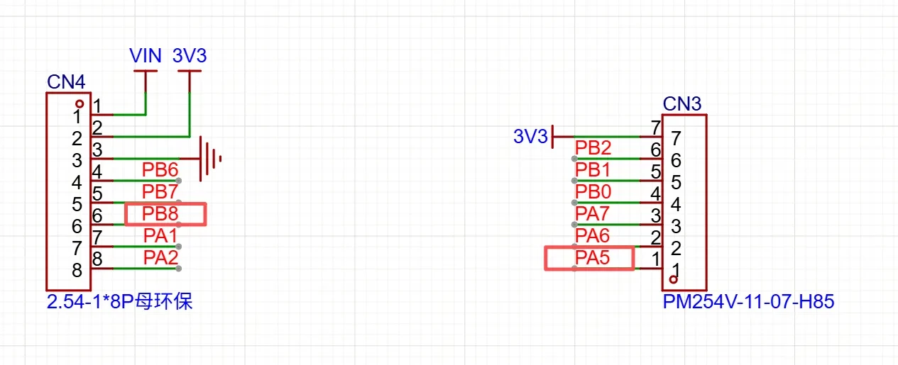
Use the following two GPIO pins as the PWM output channels.
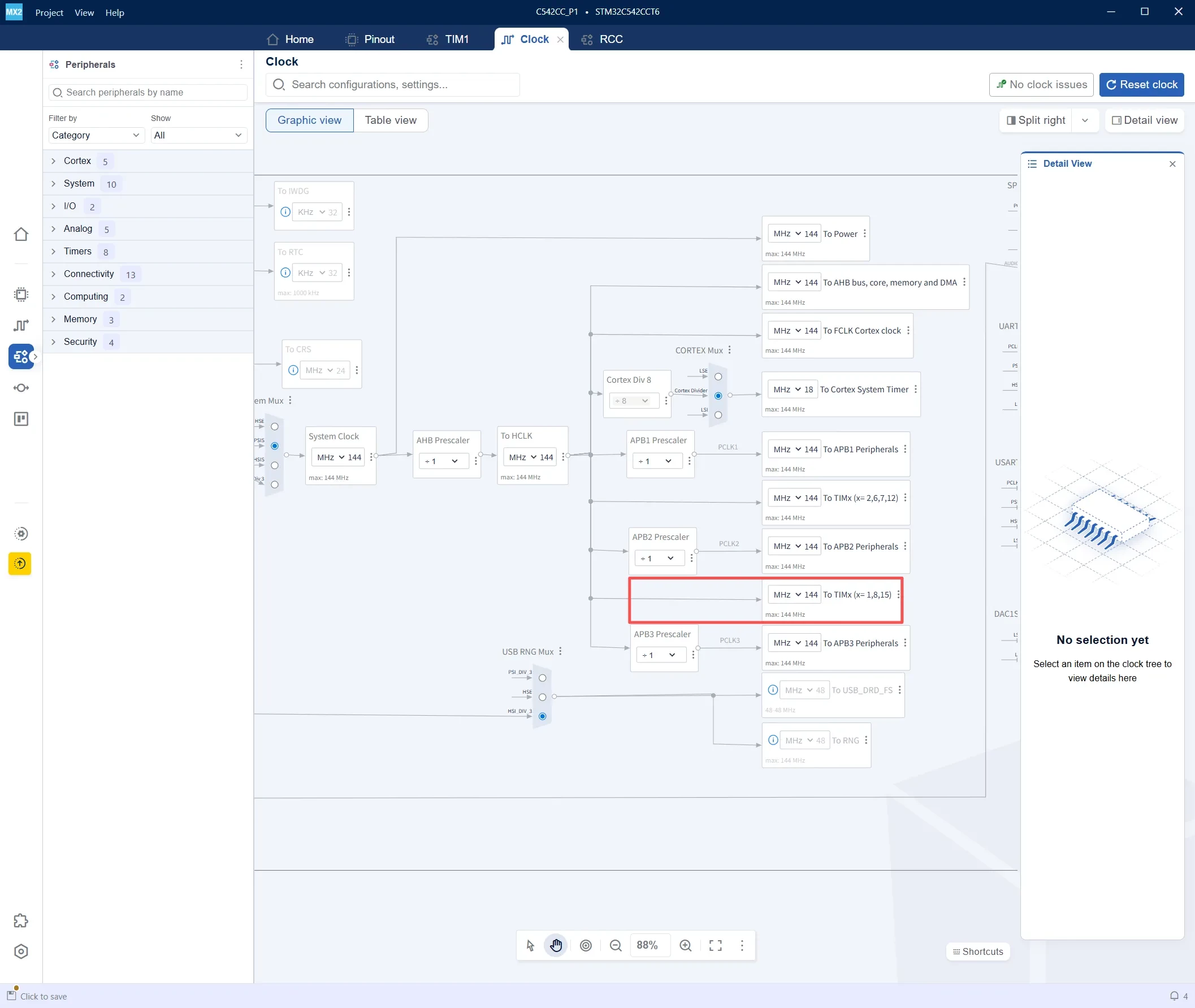
Before configuring the PSC and ARR values of TIM1, first confirm the TIM1 input clock frequency. The PWM frequency calculation depends on the timer input clock; if the clock frequency is determined incorrectly, the resulting PWM frequency will also be inaccurate.
In this example:
TIM1 Clock = 144 MHz
The TIM1 configuration procedure is as follows:
-
Click Peripherals in the left-side panel to open the peripheral configuration page.
-
Under the Timers category, select TIM1.
-
Verify that TIM1 is marked as Active, indicating that the peripheral has been enabled.
-
Set Clock Source to Internal clock source so that TIM1 uses the internal clock as its counter clock.
-
Under Channel(s), enable the required output channels, such as Channel 1 and Channel 3.
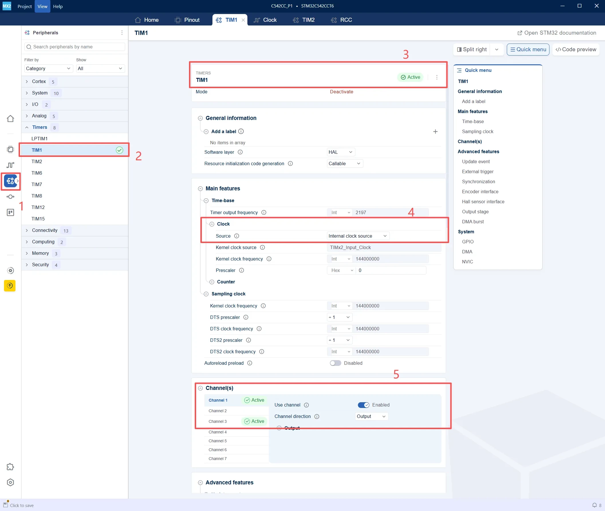
In the Channel(s) configuration section, select Channel 1 and configure it as follows:
-
Verify that Channel 1 is marked as Active, indicating that TIM1_CH1 has been enabled.
-
Set Use channel to Enabled.
-
Set Channel direction to Output so that the channel operates as an output.
-
Set Output compare mode to PWM mode 1 to generate a PWM waveform.
-
Set Pulse, which corresponds to CCR1, to configure the PWM duty cycle.
-
Set GPIO pin to Enabled so that the PWM signal is routed to the corresponding GPIO pin.
-
Set Polarity to Active high, meaning the PWM active level is high.
-
Set Idle state to Inactive, meaning the output remains inactive when the channel is idle.
-
Leave the complementary output channel CH1N set to Disabled, as complementary output is not used in this example.
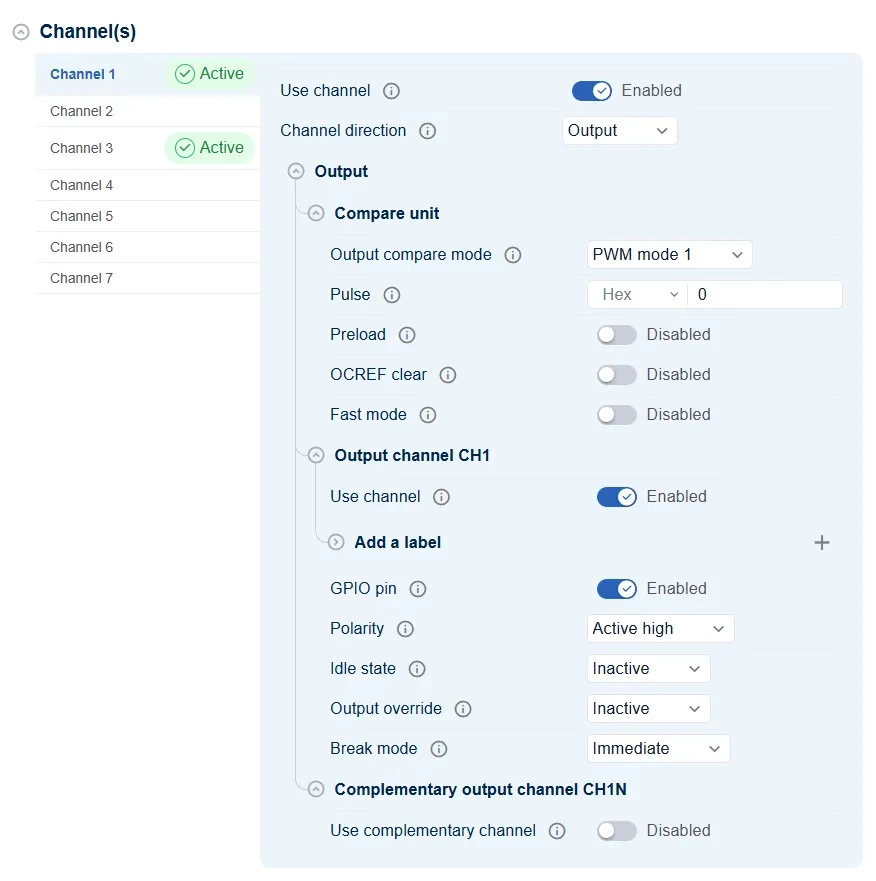
In the Channel(s) configuration section, select Channel 3 and configure it as follows:
-
Verify that Channel 3 is marked as Active, indicating that TIM1_CH3 has been enabled.
-
Set Use channel to Enabled.
-
Set Channel direction to Output so that the channel operates as an output.
-
Set Output compare mode to PWM mode 1 to generate a PWM waveform.
-
Set Pulse, which corresponds to CCR3, to configure the duty cycle of TIM1_CH3.
-
Set GPIO pin to Enabled so that the PWM signal is routed to the corresponding GPIO pin.
-
Set Polarity to Active high, meaning the PWM active level is high.
-
Set Idle state to Inactive, meaning the output remains inactive when the channel is idle.
-
The complementary output channel CH3N is not used. This example uses only the standard PWM output.
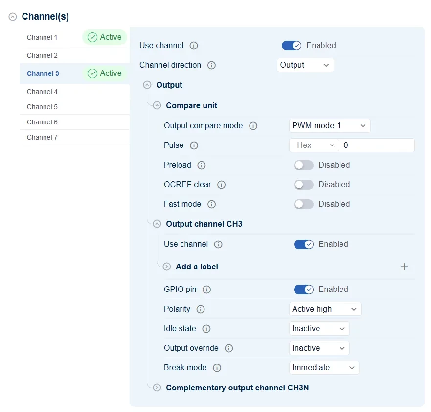
The current pin assignment is as follows:
-
TIM1_CH1 → PB8
-
TIM1_CH3 → PA5
Therefore, TIM1_CH1 is routed to PB8, while TIM1_CH3 is routed to PA5.
The GPIO configuration for both pins is essentially the same:
-
Mode: Alternate
-
Pull: No pull-up and no pull-down
-
Speed: Low
-
Output type: Push-pull
-
EXTI: Disabled
Generate the Project
-
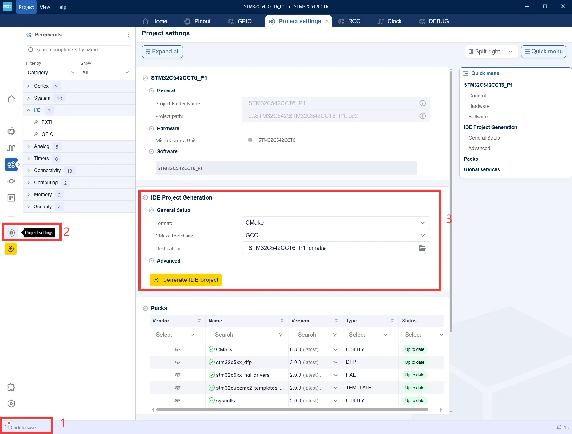
After modifying the configuration, a Click to save prompt appears in the lower-left corner. Save the current project configuration first.
-
Click Project settings in the left-side panel to open the project generation settings.
-
Under IDE Project Generation, select the desired project format and toolchain. In this example, choose CMake + GCC, then click Generate IDE project to generate the project.
Import the Project into STM32CubeIDE
-
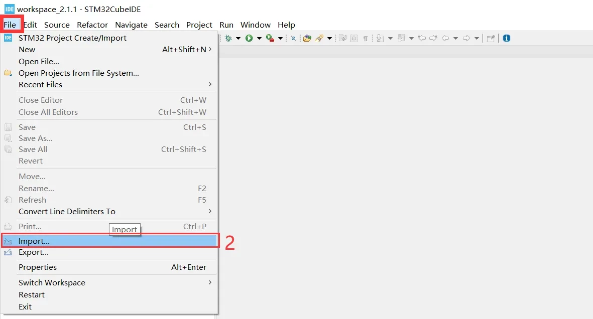
Open STM32CubeIDE and click File from the menu bar.
-
Select Import... to import the CMake project generated by STM32CubeMX2.
-
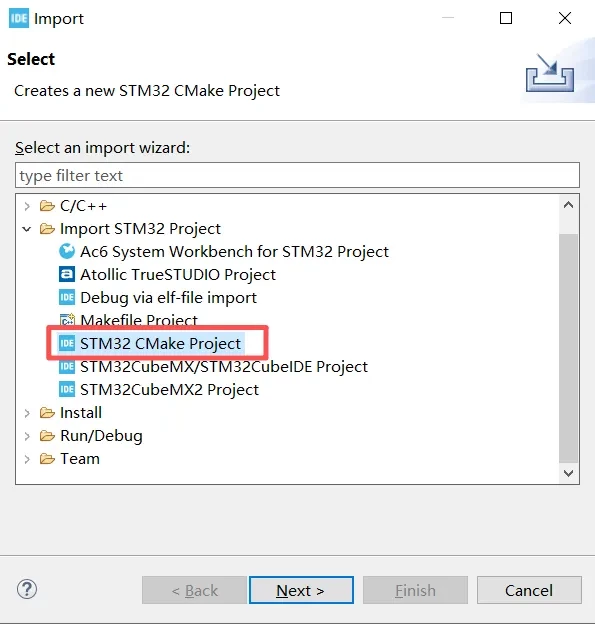
In the Import dialog, expand Import STM32 Project.
-
Select STM32 CMake Project.
-
Click Next to proceed to the CMake project location selection page.
-
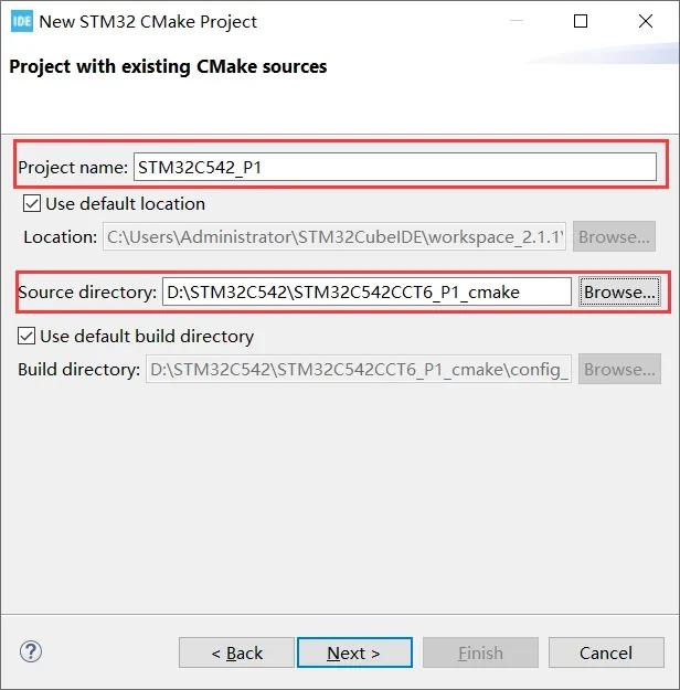
Project name: Enter the name that will be displayed for the project in STM32CubeIDE.
-
Source directory: Select the CMake project directory generated by STM32CubeMX2.
-
Click Next to continue the import process.
-
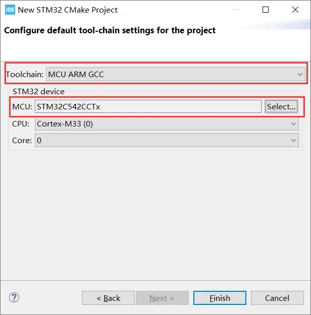
Toolchain: Select MCU ARM GCC to use the ARM GCC toolchain for building the project.
-
MCU: Verify that the selected device is STM32C542CCTx, matching the MCU configured in STM32CubeMX2.
-
CPU/Core: Confirm that the CPU is Cortex-M33 and the Core is Core 0.
-
Click Finish to complete the import of the CMake project.
How PWM Mode Works
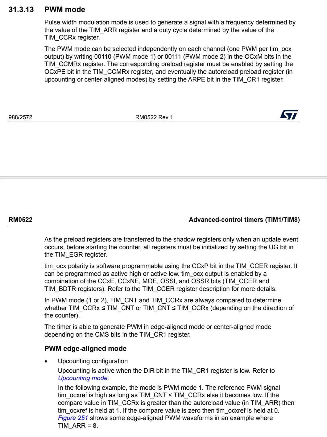
According to the PWM mode section in RM0522, PWM mode is used to generate a periodic output signal. The signal frequency is determined by the TIM_ARR auto-reload register, while the duty cycle is determined by the TIM_CCRx capture/compare register.
The reference manual also states that PWM mode can be selected independently for each channel. This means that a single TIM peripheral can provide multiple PWM output channels, for example:
-
TIM1_CH1 -
TIM1_CH2 -
TIM1_CH3 -
TIM1_CH4
Each channel can be configured independently as PWM mode 1 or PWM mode 2. This tutorial uses PWM mode 1.
In up-counting mode, PWM mode 1 can be understood as follows:
-
When
TIM_CNT < TIM_CCRx, the PWM output is at the active level. -
When
TIM_CNT >= TIM_CCRx, the PWM output is at the inactive level.
Because the PWM output polarity was previously configured as Active high in STM32CubeMX2, the active level is a high level in this example.
Therefore, within one PWM period, increasing the value of TIM_CCRx extends the high-level duration and increases the duty cycle.
Standard PWM Mode 1
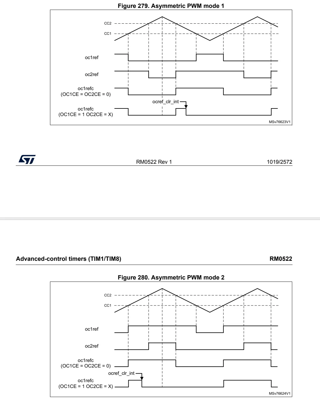
In PWM mode 1, the waveform is controlled primarily by a capture/compare register. For example:
-
TIM1_CH1 → CCR1
In this mode:
-
The PWM frequency is determined by the ARR register.
-
The PWM duty cycle is determined by the CCR1 register.
This configuration is suitable for common applications such as LED dimming, buzzer control, and other standard PWM output scenarios.
The PWM frequency is calculated using the following formula:
[
\text{PWM Frequency} = \frac{\text{TIM Input Clock}}{(\text{PSC} + 1) \times (\text{ARR} + 1)}
]
The PWM duty cycle is calculated as:
[
\text{Duty Cycle} = \frac{\text{CCR}}{\text{ARR} + 1} \times 100%
]
Definitions
This experiment is based on the STM32C542CCT6 and uses STM32CubeMX2 to configure the TIM1 PWM output.
Two TIM1 output channels are used:
TIM1_CH1 -> PB8
TIM1_CH3 -> PA5
Both TIM1_CH1 and TIM1_CH3 are configured in PWM mode 1. The PWM frequency and duty cycle are dynamically adjusted using the built-in HAL2 functions.
The following header files are used in the code:
#include <stdio.h>
#include "mx_tim1.h"
The TIM1 input clock is defined as 144 MHz. Therefore, 144 MHz is used as the input clock for the subsequent PWM frequency calculations.
To generate a 1000 Hz PWM signal, it is recommended to set ARR to 999.
In this configuration, one PWM period contains:
ARR + 1 = 999 + 1 = 1000
counter ticks, which makes the duty-cycle calculation easier.
The PWM frequency is calculated using the following formula:
PWM Frequency = TIM1_CLK / ((PSC + 1) × (ARR + 1))
When:
TIM1_CLK = 144 MHz
PSC      = 143
ARR      = 999
the PWM frequency is calculated as follows:
PWM Frequency = 144,000,000 / ((143 + 1) × (999 + 1))
              = 144,000,000 / (144 × 1000)
              = 1000 Hz
Add the following code.
/* Private define ------------------------------------------------------------*/
#define TIM1_CLK_HZ        144000000UL

/*
 * 本实验固定 ARR = 9999
 * 这样一个 PWM 周期为 10000 个计数点,方便计算占空比
 */
#define TIM1_PWM_ARR       9999UL

/* Private function prototypes -----------------------------------------------*/
static hal_status_t TIM1_SetPSC_ARR(uint32_t psc, uint32_t arr);
static hal_status_t TIM1_SetFrequency(uint32_t freq_hz);
static hal_status_t TIM1_SetChannelDuty(hal_tim_channel_t channel,
                                        uint32_t arr,
                                        uint32_t duty_percent);
static hal_status_t TIM1_PWM_Start_CH1_CH3(void);
Modifying PSC and ARR
The code defines a TIM1_SetPSC_ARR() function to modify the TIM1 prescaler and auto-reload values.
This function performs the following four operations:
-
Calls
mx_tim1_gethandle()to obtain the TIM1 handle. -
Uses
HAL_TIM_SetPrescaler()to modifyTIM1_PSC. -
Uses
HAL_TIM_SetPeriod()to modifyTIM1_ARR. -
Uses
HAL_TIM_SetCounter()to reset the counter to zero.
/**
  * @brief  使用 HAL2 自带函数修改 TIM1 PSC 和 ARR
  * @param  psc: TIM1 预分频值
  * @param  arr: TIM1 自动重装载值
  * @retval HAL status
  */
static hal_status_t TIM1_SetPSC_ARR(uint32_t psc, uint32_t arr)
{
    hal_tim_handle_t *htim1 = mx_tim1_gethandle();

    if (htim1 == NULL)
    {
        return HAL_ERROR;
    }

    /*
     * 使用 HAL2 自带函数修改 PSC 和 ARR
     * PSC 影响计数频率
     * ARR 影响 PWM 周期
     */
    if (HAL_TIM_SetPrescaler(htim1, psc) != HAL_OK)
    {
        return HAL_ERROR;
    }

    if (HAL_TIM_SetPeriod(htim1, arr) != HAL_OK)
    {
        return HAL_ERROR;
    }

    /*
     * 修改参数后,将计数器清零,方便观察 PWM 输出变化
     */
    if (HAL_TIM_SetCounter(htim1, 0) != HAL_OK)
    {
        return HAL_ERROR;
    }

    return HAL_OK;
}
Automatically Calculating PSC from the Target Frequency
For easier use, the code further defines a TIM1_SetFrequency() function.
This function takes the target PWM frequency as its input and automatically calculates the PSC value based on the current ARR value.
The PWM frequency formula is:
PWM Frequency = TIM1_CLK / ((PSC + 1) × (ARR + 1))
Rearranging the formula gives:
PSC + 1 = TIM1_CLK / (PWM Frequency × (ARR + 1))
For example:
TIM1_SetFrequency(1000);
When:
TIM1_CLK = 144 MHz
ARR      = 999
the calculated result is:
PSC = 143
Therefore, the final PWM output frequency is 1000 Hz.
/**
  * @brief  根据目标频率自动计算 PSC,并设置 TIM1 频率
  * @param  freq_hz: 目标 PWM 频率,单位 Hz
  * @retval HAL status
  */
static hal_status_t TIM1_SetFrequency(uint32_t freq_hz)
{
    uint32_t arr = TIM1_PWM_ARR;
    uint32_t psc;

    if (freq_hz == 0U)
    {
        return HAL_INVALID_PARAM;
    }

    /*
     * PWM 频率 = TIM1_CLK / ((PSC + 1) * (ARR + 1))
     *
     * 反推:
     * PSC + 1 = TIM1_CLK / (PWM频率 * (ARR + 1))
     */
    psc = TIM1_CLK_HZ / (freq_hz * (arr + 1U));

    if (psc == 0U)
    {
        psc = 1U;
    }

    psc = psc - 1U;

    return TIM1_SetPSC_ARR(psc, arr);
}
Setting the Channel Duty Cycle
The PWM duty cycle is determined by CCRx, which corresponds to the Pulse value.
The code defines a TIM1_SetChannelDuty() function to configure the duty cycle of a specified TIM1 channel.
The duty-cycle formula is:
Duty Cycle = Pulse / (ARR + 1) × 100%
Rearranging the formula gives:
Pulse = (ARR + 1) × Duty / 100
For example, when:
ARR  = 999
Duty = 25%
the Pulse value is:
Pulse = (999 + 1) × 25 / 100
      = 250
Therefore, the duty cycle of TIM1_CH1 is 25%.
Similarly, when:
ARR  = 999
Duty = 75%
the Pulse value is:
Pulse = (999 + 1) × 75 / 100
      = 750
Therefore, the duty cycle of the corresponding channel is 75%.
/**
  * @brief  设置 TIM1 某一个通道的占空比
  * @param  channel: HAL_TIM_CHANNEL_1 / HAL_TIM_CHANNEL_3 等
  * @param  arr: 当前 ARR 值
  * @param  duty_percent: 占空比,范围 0~100
  * @retval HAL status
  */
static hal_status_t TIM1_SetChannelDuty(hal_tim_channel_t channel,
                                        uint32_t arr,
                                        uint32_t duty_percent)
{
    hal_tim_handle_t *htim1 = mx_tim1_gethandle();
    uint32_t pulse;

    if (htim1 == NULL)
    {
        return HAL_ERROR;
    }

    if (duty_percent > 100U)
    {
        duty_percent = 100U;
    }

    /*
     * 占空比 = Pulse / (ARR + 1) * 100%
     *
     * 所以:
     * Pulse = (ARR + 1) * Duty / 100
     */
    pulse = ((arr + 1U) * duty_percent) / 100U;

    /*
     * 使用 HAL2 自带函数修改 CCRx / Pulse
     *
     * TIM1_CH1 -> CCR1
     * TIM1_CH3 -> CCR3
     */
    if (HAL_TIM_OC_SetCompareUnitPulse(
            htim1,
            hal_tim_oc_channel_to_compare_unit(channel),
            pulse) != HAL_OK)
    {
        return HAL_ERROR;
    }

    return HAL_OK;
}
Starting the PWM Output
After configuring the PWM frequency and duty cycle, the TIM1 output channels and counter must be started.
The following components are started:
TIM1_CH1
TIM1_CH3
TIM1 counter
HAL_TIM_OC_StartChannel() is used to start the specified output channel, while HAL_TIM_Start() is used to start the TIM1 counter.
/**
  * @brief  启动 TIM1 CH1 和 CH3 PWM 输出
  * @retval HAL status
  */
static hal_status_t TIM1_PWM_Start_CH1_CH3(void)
{
    hal_tim_handle_t *htim1 = mx_tim1_gethandle();

    if (htim1 == NULL)
    {
        return HAL_ERROR;
    }

    /*
     * 启动 TIM1_CH1 输出
     */
    if (HAL_TIM_OC_StartChannel(htim1, HAL_TIM_CHANNEL_1) != HAL_OK)
    {
        return HAL_ERROR;
    }

    /*
     * 启动 TIM1_CH3 输出
     */
    if (HAL_TIM_OC_StartChannel(htim1, HAL_TIM_CHANNEL_3) != HAL_OK)
    {
        return HAL_ERROR;
    }

    /*
     * 启动 TIM1 计数器
     */
    if (HAL_TIM_Start(htim1) != HAL_OK)
    {
        return HAL_ERROR;
    }

    return HAL_OK;
}
Main Program
/**
  * brief:  The application entry point.
  * retval: none but we specify int to comply with C99 standard
  */
int main(void)
{
  /** System Init: this code placed in targets folder initializes your system.
    * It calls the initialization (and sets the initial configuration) of the peripherals.
    * You can use STM32CubeMX to generate and call this code or not in this project.
    * It also contains the HAL initialization and the initial clock configuration.
    */
  if (mx_system_init() != SYSTEM_OK)
  {
    return (-1);
  }
  else
  {


    /*
     * TIM1_CH1 -> PB8
     * TIM1_CH3 -> PA5
     *
     * 当前配置:
     * TIM1_CLK = 144 MHz
     * ARR = 9999
     */

    /*
     * 设置 PWM 频率为 1Hz
     *
     * PWM频率 = 144MHz / ((PSC + 1) * (ARR + 1))
     * ARR = 9999
     * 当 freq = 1Hz 时,PSC = 14399
     */
    if (TIM1_SetFrequency(1) != HAL_OK)
    {
        printf("TIM1_SetFrequency failed\r\n");
    }

    /*
     * 设置多通道占空比
     *
     * CH1 = 25%
     * CH3 = 75%
     */
    if (TIM1_SetChannelDuty(HAL_TIM_CHANNEL_1, TIM1_PWM_ARR, 25) != HAL_OK)
    {
        printf("TIM1 CH1 duty set failed\r\n");
    }

    if (TIM1_SetChannelDuty(HAL_TIM_CHANNEL_3, TIM1_PWM_ARR, 75) != HAL_OK)
    {
        printf("TIM1 CH3 duty set failed\r\n");
    }

    /*
     * 启动 TIM1 CH1 和 CH3 PWM 输出
     */
    if (TIM1_PWM_Start_CH1_CH3() != HAL_OK)
    {
        printf("TIM1 PWM start failed\r\n");
    }
    HAL_Delay(5000);
    while (1)
    {
        printf("TIM1 PWM: 1000Hz, CH1=25%%, CH3=75%%\r\n");

        /*
         * 设置 TIM1 PWM 频率为 1000Hz
         *
         * TIM1_CLK = 144MHz
         * ARR = 999
         * PSC = 143
         *
         * PWM频率 = 144MHz / ((143 + 1) * (999 + 1))
         *         = 1000Hz
         */
        TIM1_SetFrequency(1000);

        /*
         * CH1 输出 25% 占空比
         * CH3 输出 75% 占空比
         */
        TIM1_SetChannelDuty(HAL_TIM_CHANNEL_1, TIM1_PWM_ARR, 25);
        TIM1_SetChannelDuty(HAL_TIM_CHANNEL_3, TIM1_PWM_ARR, 75);

        HAL_Delay(3000);
//
//        printf("TIM1 PWM: 1000Hz, CH1=50%%, CH3=50%%\r\n");
//
//        TIM1_SetFrequency(1000);
//        TIM1_SetChannelDuty(HAL_TIM_CHANNEL_1, TIM1_PWM_ARR, 50);
//        TIM1_SetChannelDuty(HAL_TIM_CHANNEL_3, TIM1_PWM_ARR, 50);
//
//        HAL_Delay(3000);
//
//        printf("TIM1 PWM: 1000Hz, CH1=75%%, CH3=25%%\r\n");
//
//        TIM1_SetFrequency(1000);
//        TIM1_SetChannelDuty(HAL_TIM_CHANNEL_1, TIM1_PWM_ARR, 75);
//        TIM1_SetChannelDuty(HAL_TIM_CHANNEL_3, TIM1_PWM_ARR, 25);
//
//        HAL_Delay(3000);
    }
  }
} /* end main */
Demonstration
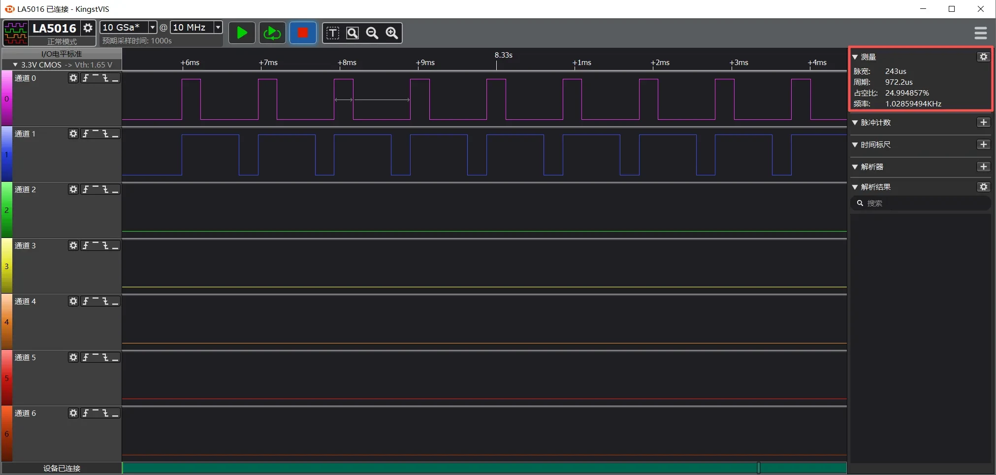
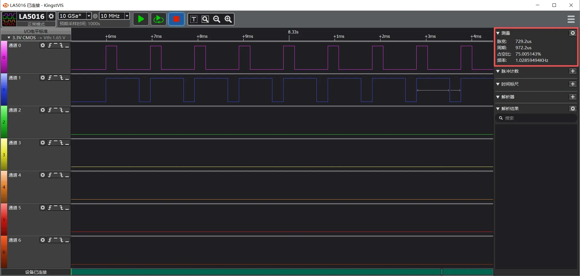
Use an oscilloscope or logic analyzer to measure the PWM signals on PB8 and PA5.
The two PWM channels have the same output frequency. Initially, the following PWM signals are generated:
TIM1_CH1: 1 Hz, 25% duty cycle
TIM1_CH3: 1 Hz, 75% duty cycle
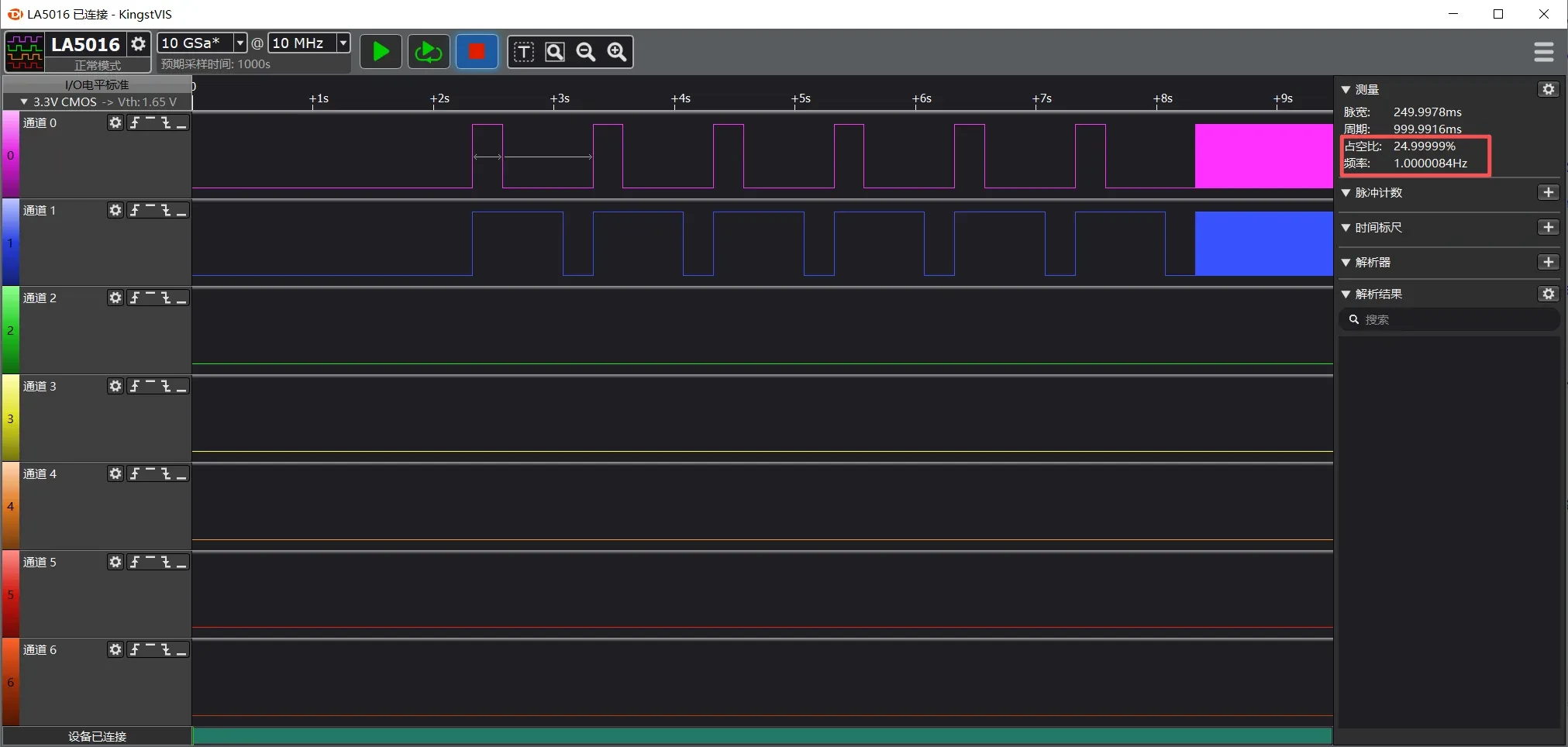
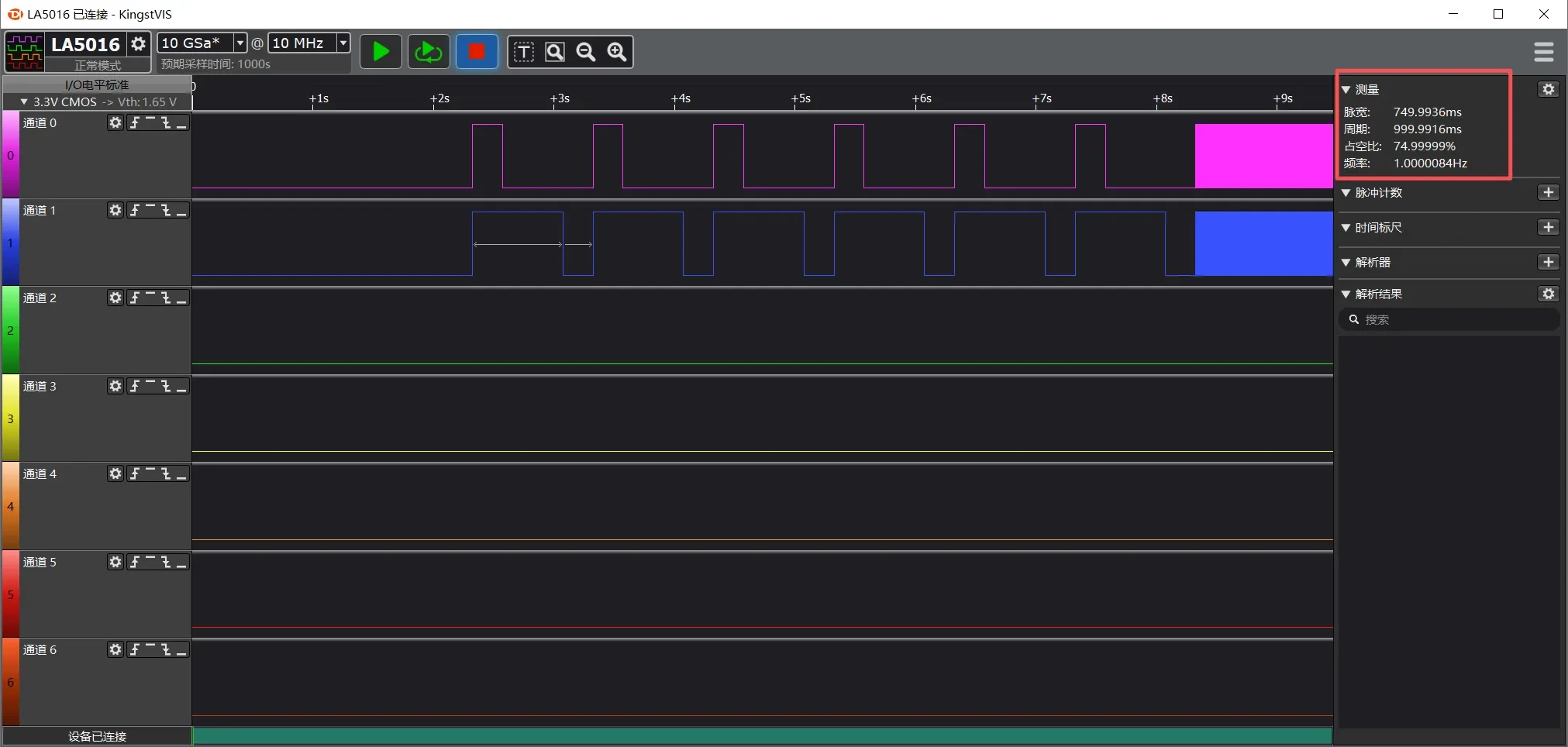
The output is then changed to two 1 kHz PWM signals:
TIM1_CH1: 1 kHz, 25% duty cycle
TIM1_CH3: 1 kHz, 75% duty cycle