STM32C542 Development (3) — UART Configuration and printf Redirection
Overview
In traditional STM32 development, we typically use STM32CubeMX to configure the USART peripheral and redirect printf() to the serial port for debugging output. With the STM32C5 series, ST introduces the new STM32CubeMX2 configuration tool and the HAL2 driver framework. Compared with the legacy HAL, the project structure and some API names have changed, so the UART configuration process and application code require slight modifications accordingly.
Hardware Preparation
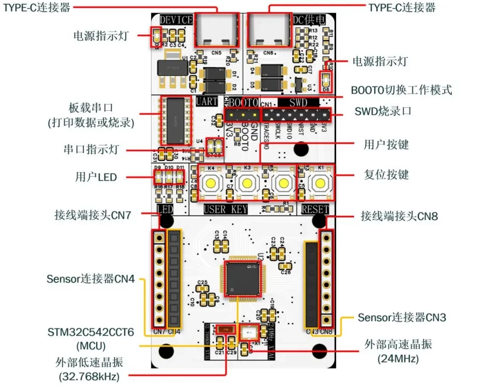
First, prepare a development board. In this tutorial, I use a custom-designed development board. If you are interested in obtaining one, you can apply for a sample.
The main controller is the STM32C542CCT6.
Reference Project
The reference project is available on GitHub:
https://github.com/CoreMaker-lab/STM32C542_SENSOR
Creating a Project with STM32CubeMX2
Use STM32CubeMX2 to generate the example project. The MCU used in this tutorial is the STM32C542CCT6.
-
Open STM32CubeMX2 and go to the Home page.
-
Click MCU to create a new project based on a specific device.
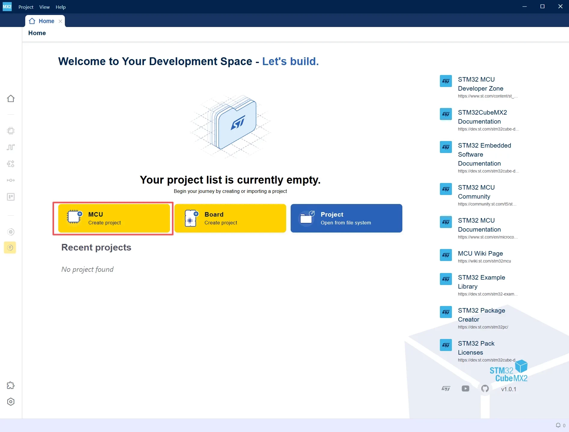
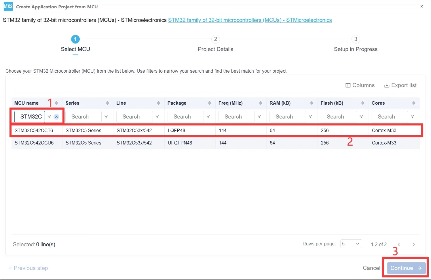
Enter STM32C542CCT6 in the MCU name field. Select the corresponding STM32C5 device from the list, then click Continue to proceed to the project configuration page.
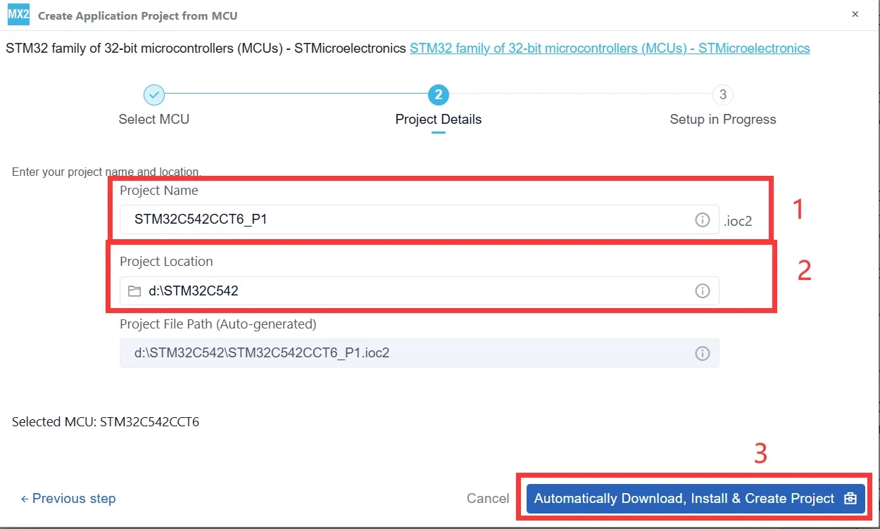
After entering the project name and selecting the project directory, click Automatically Download, Install & Create Project. STM32CubeMX2 will automatically download the required software packages and generate the project.
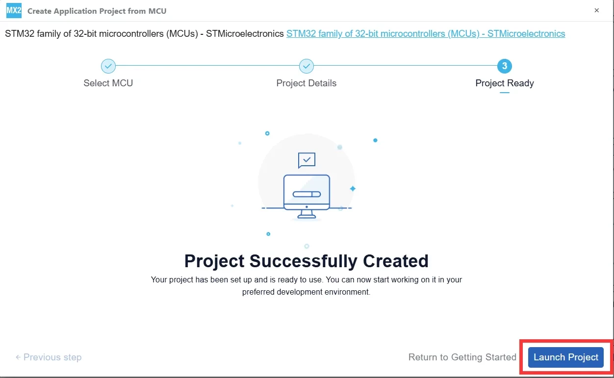
After STM32CubeMX2 displays the Project Successfully Created message, click Launch Project in the lower-right corner to open the project configuration interface.
Clock Configuration
-
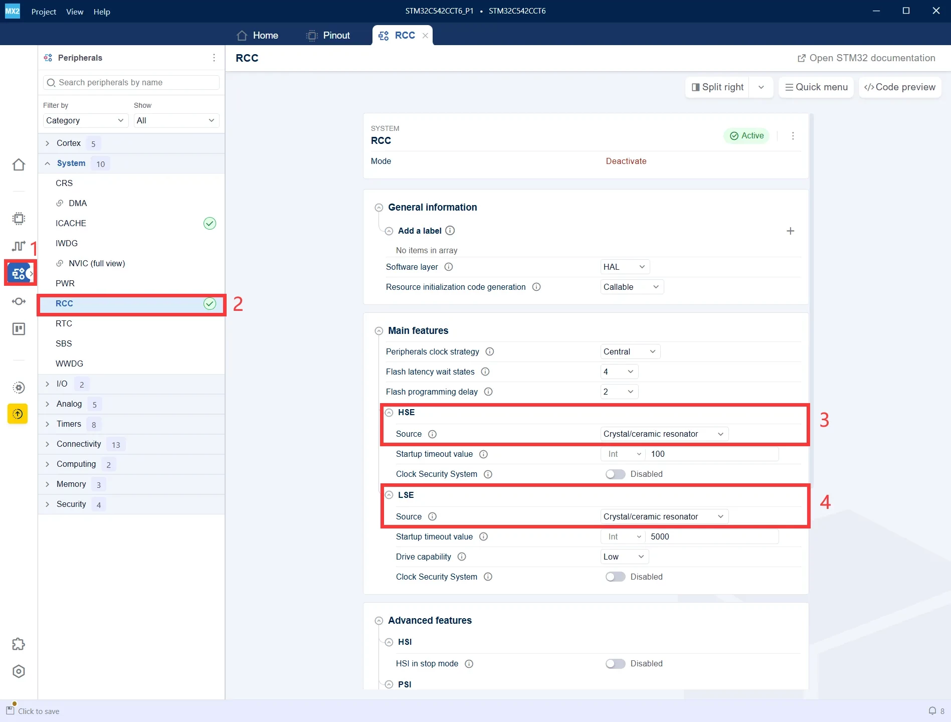
In the left-side panel, click Peripherals to open the peripheral configuration page.
-
Under the System category, select RCC to configure the system clock source.
-
Set HSE Source to Crystal/Ceramic Resonator to enable the external high-speed oscillator (HSE).
-
Set LSE Source to Crystal/Ceramic Resonator to enable the external low-speed oscillator (LSE).
-
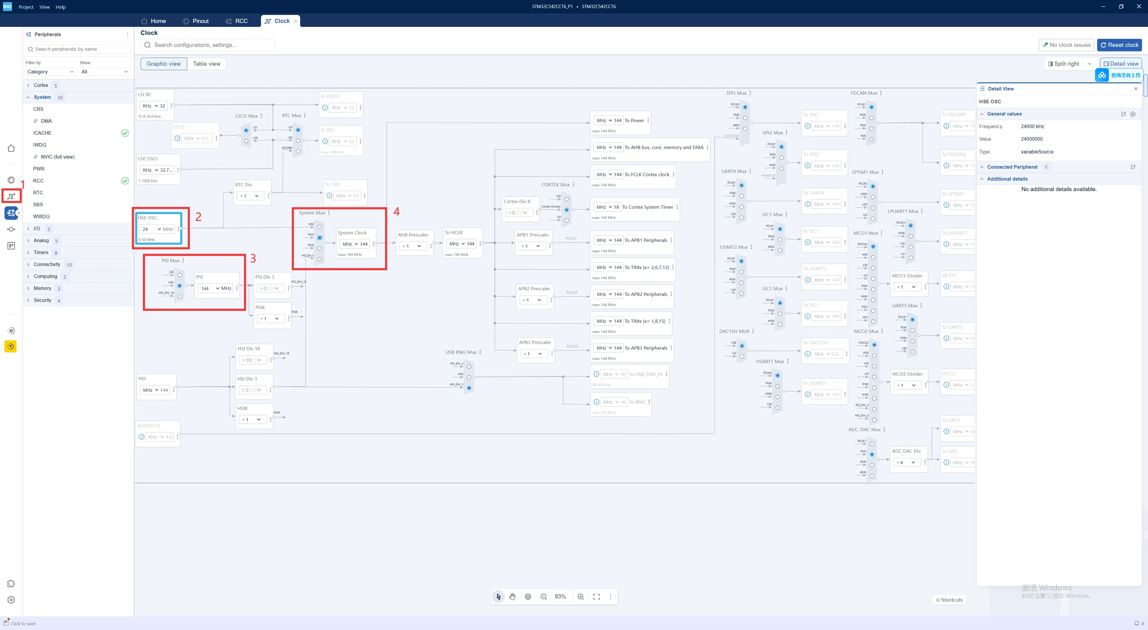
Click the Clock icon in the left-side panel to open the Clock Configuration page.
-
Set HSE OSC to 24 MHz to match the external high-speed crystal frequency.
-
Configure PSI Mux / PLL to select the PLL clock source and generate the desired system clock frequency.
-
Set System Mux to use the PLL as the system clock source. In this example, the system clock is configured to 144 MHz.
DEBUG Configuration
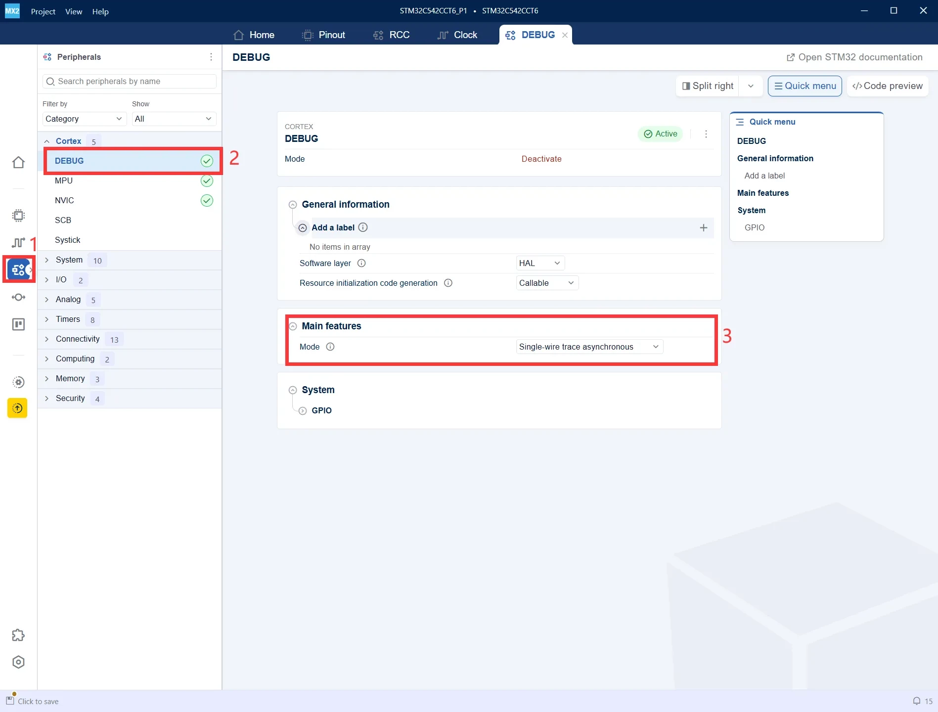
In the Peripherals panel, navigate to Cortex → DEBUG, then set Mode to Single-wire trace asynchronous. This enables program downloading, on-chip debugging, and Trace debugging in subsequent development.
UART Configuration
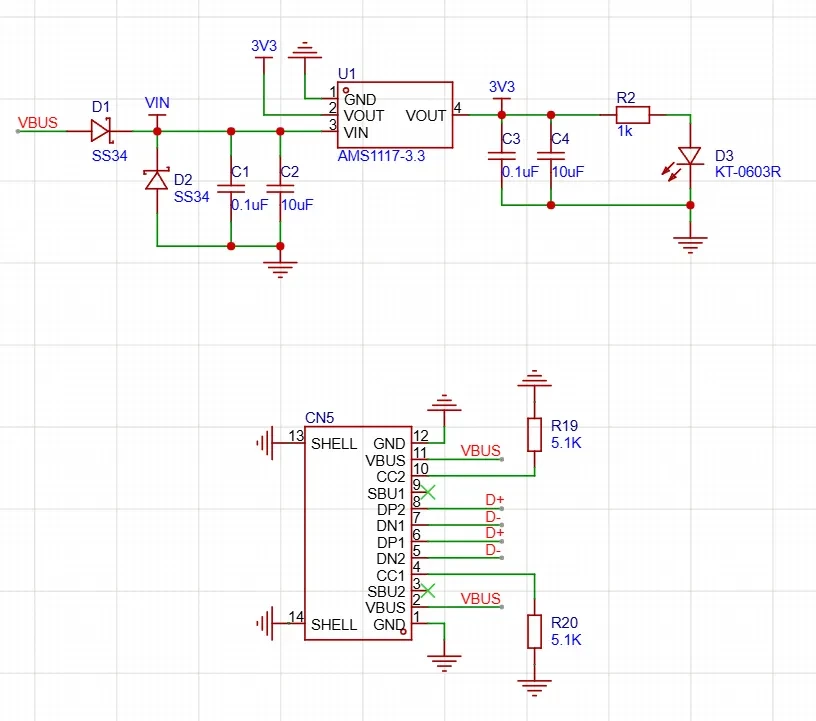
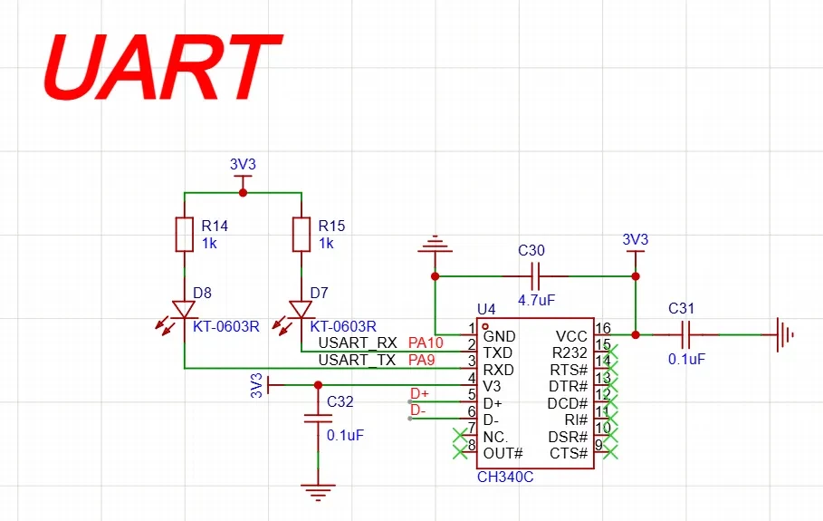
Refer to the schematic and note that PA9 and PA10 are connected to the UART interface on the development board.
-
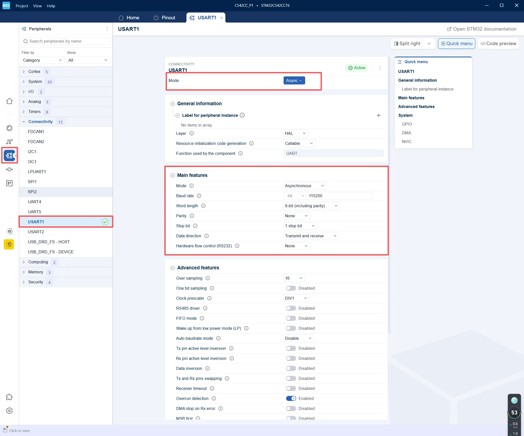
In the Peripherals panel, navigate to Connectivity → USART1.
-
Set Mode to Async to configure USART1 for asynchronous communication.
-
Verify that Function used by the component is displayed as UART, indicating that USART1 uses the UART HAL driver in asynchronous mode.
-
Configure the UART parameters as follows:
-
Baud Rate: 115200
-
Word Length: 8 Bits
-
Parity: None
-
Stop Bits: 1
-
Mode: TX and RX
-
-
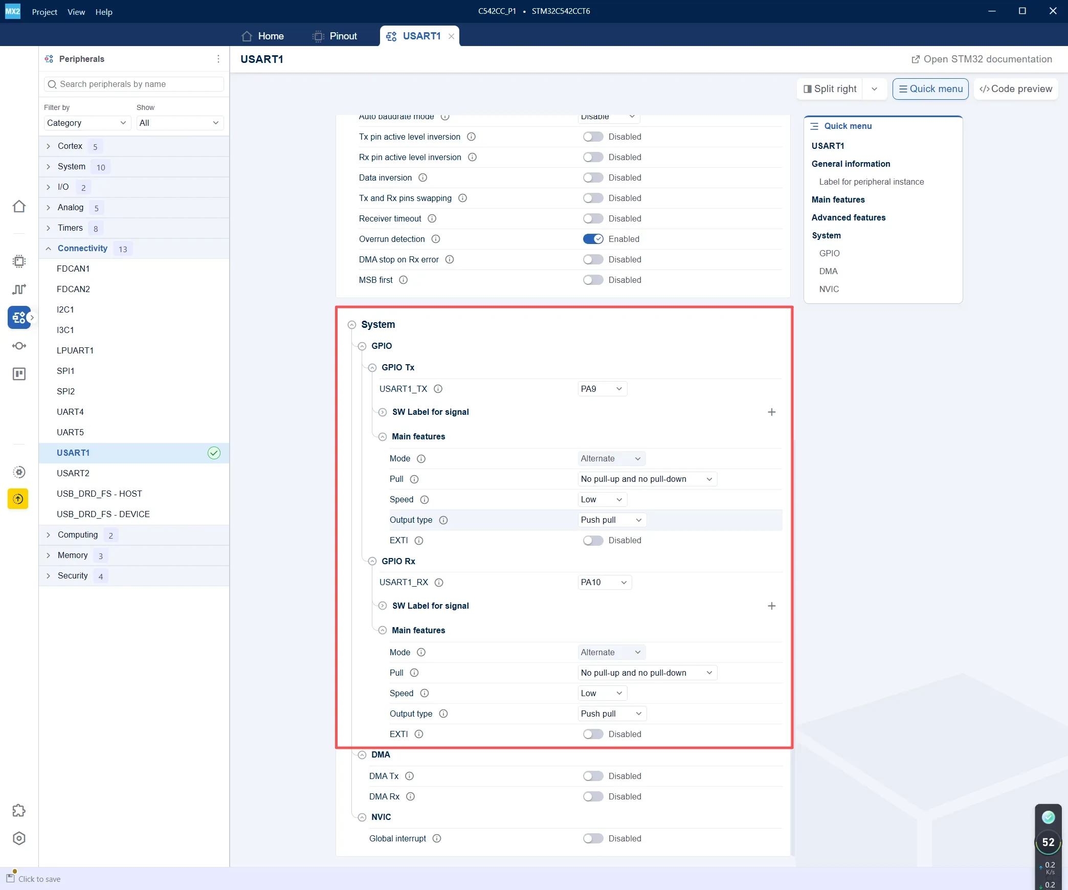
For GPIO Tx, assign USART1_TX to PA9.
-
For GPIO Rx, assign USART1_RX to PA10.
-
Configure both PA9 and PA10 in Alternate Function mode.
-
Set Pull to No pull-up and no pull-down, Output type to Push-pull, and Speed to Low.
Generate the Project
-
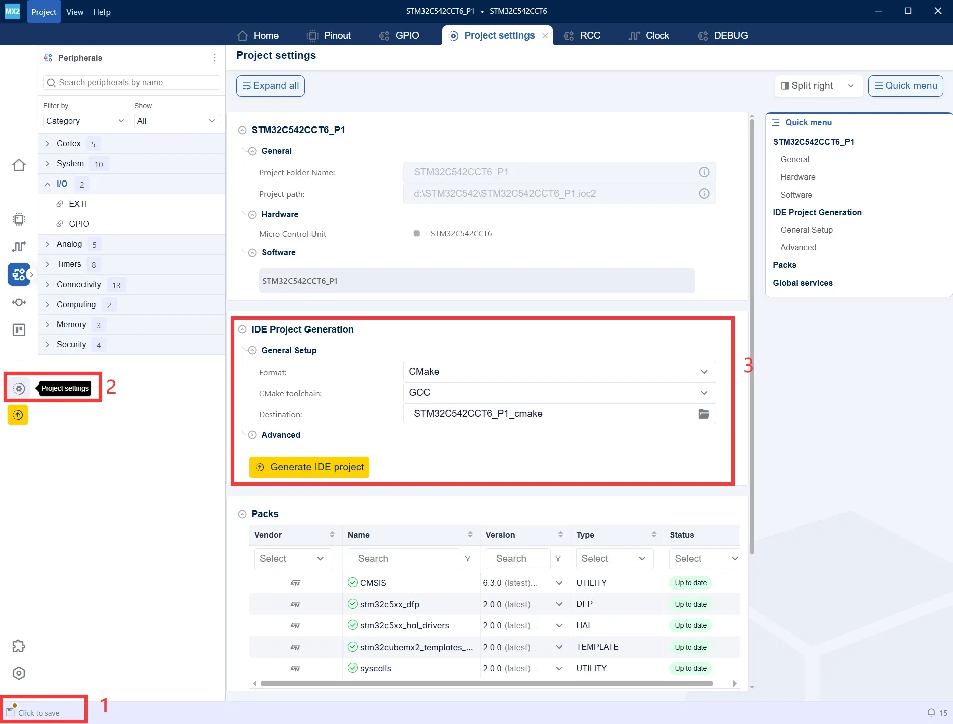
After modifying the configuration, a Click to save prompt appears in the lower-left corner. Save the current project configuration first.
-
Click Project settings in the left-side panel to open the project generation settings.
-
Under IDE Project Generation, select the desired project format and toolchain. In this example, choose CMake + GCC, then click Generate IDE project to generate the project.
Import the Project into STM32CubeIDE
-
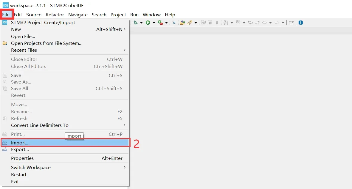
Open STM32CubeIDE and click File from the menu bar.
-
Select Import... to import the CMake project generated by STM32CubeMX2.
-
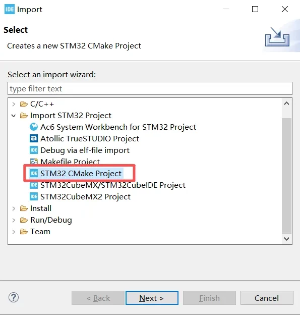
In the Import dialog, expand Import STM32 Project.
-
Select STM32 CMake Project.
-
Click Next to proceed to the CMake project location selection page.
-
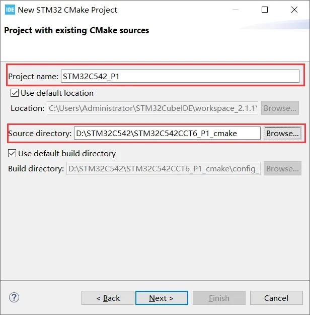
Project name: Enter the name that will be displayed for the project in STM32CubeIDE.
-
Source directory: Select the CMake project directory generated by STM32CubeMX2.
-
Click Next to continue the import process.
-
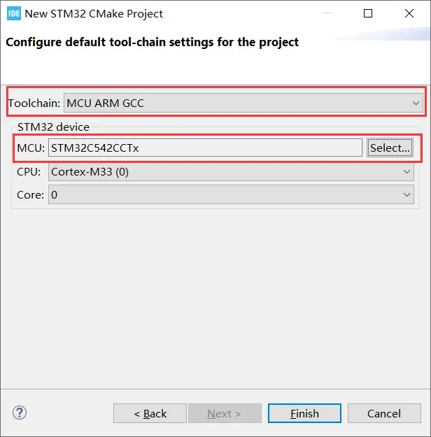
Toolchain: Select MCU ARM GCC to use the ARM GCC toolchain for building the project.
-
MCU: Verify that the selected device is STM32C542CCTx, matching the MCU configured in STM32CubeMX2.
-
CPU/Core: Confirm that the CPU is Cortex-M33 and the Core is Core 0.
-
Click Finish to complete the import of the CMake project.
Set the Project Encoding
-
In the Project Explorer, select the current project.
-
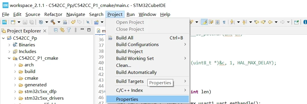
Click Project from the menu bar.
-
Select Properties to open the project properties dialog.
-
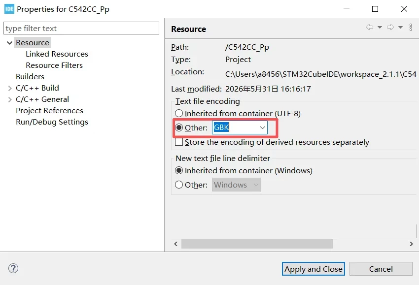
In the Project Properties dialog, select Resource.
-
Under Text file encoding, choose Other.
-
Set the encoding to GBK.
-
Click Apply and Close to save the settings.
Add Header Files
Add the required header files to main.c.
#include "mx_usart1.h"
#include <stdio.h>
#include <string.h>
printf() Redirection
To redirect the output of printf() to USART1, you need to override the _write() function.
In GCC-based projects, printf() ultimately calls _write() to output characters. Therefore, by calling HAL_UART_Transmit() inside the _write() function, all data printed by printf() can be transmitted through the UART.
int _write(int file, char *ptr, int len)
{
    hal_uart_handle_t *huart1 = mx_usart1_uart_gethandle();

    if (huart1 != NULL)
    {
        HAL_UART_Transmit(huart1, ptr, len, 1000);
    }

    return len;
}
UART Print Test
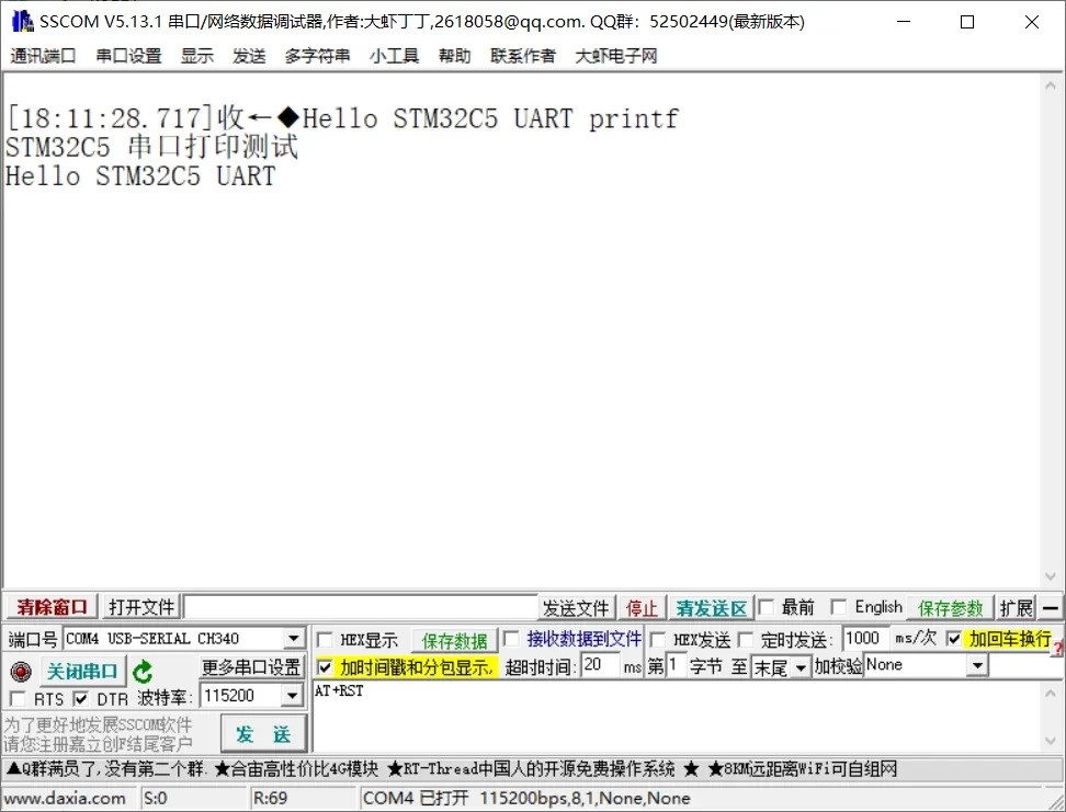
After mx_system_init() has completed, you can directly call printf() to verify that UART output is working correctly.
	hal_uart_handle_t *huart1 = mx_usart1_uart_gethandle();

	printf("Hello STM32C5 UART printf\r\n");
	printf("STM32C5 串口打印测试\r\n");
	char msg[] = "Hello STM32C5 UART\r\n";

	HAL_UART_Transmit(huart1, msg, strlen(msg), 1000);
Demonstration