STM32C542 Development (2) — BOOT_SEL Configuration
Overview
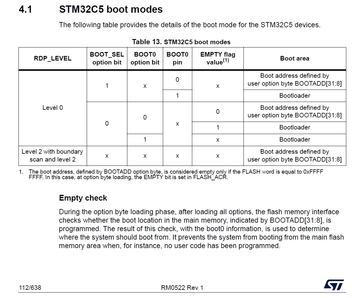
In practical project development and mass-production maintenance, in addition to using ST-LINK for programming, firmware updates are often performed through interfaces such as USART, USB DFU, SPI, or FDCAN. In these cases, the MCU must first enter the factory-programmed System Memory Bootloader before the Flash memory can be programmed through these interfaces. For the STM32C5 series, whether the external BOOT0 pin is used to enter the Bootloader is closely related to the BOOT_SEL setting in the Option Bytes.
Simply put, BOOT_SEL is used to select the source of the BOOT0 signal. When BOOT_SEL enables the external BOOT0 pin, the MCU can enter the System Memory Bootloader by pulling BOOT0 high and resetting the device. When BOOT_SEL selects the internal Option Bit, the boot mode is determined by the BOOT0 configuration in the Option Bytes. Therefore, understanding the relationship between BOOT_SEL, the BOOT0 pin, and the System Memory Bootloader is important for subsequent firmware programming through USART or USB.
Hardware Preparation
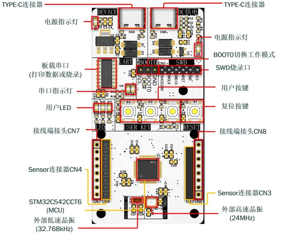
First, prepare a development board. In this tutorial, I use a custom-designed development board. Samples are available upon request.
The main MCU is STM32C542CCT6.
Reference Project
BOOT_SEL Overview
BOOT_SEL is a boot configuration option in the STM32C5 Option Bytes that determines the source of the BOOT0 signal.
- When BOOT_SEL = 1, the BOOT0 signal is controlled by the external BOOT0 pin, which is the traditional boot mechanism used by most STM32 devices.
- When BOOT_SEL = 0, the BOOT0 signal is determined by the BOOT0 option bit in the Option Bytes. In this mode, the external BOOT0 pin is no longer the primary source for boot mode selection.
According to RM0522, during startup the STM32C5 determines the boot address based on the BOOT0 pin or the BOOT0 option bit, together with the BOOT_SEL option bit and BOOTADD[31:8]. As a result, the device can boot either from the user Flash or from the System Memory Bootloader.
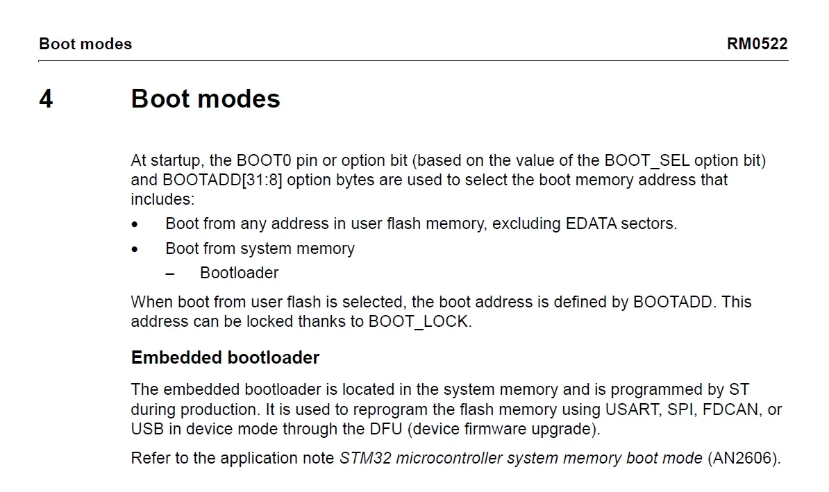
BOOT_SEL determines the source of the BOOT0 signal. BOOT0 determines whether the MCU enters the Bootloader. The EMPTY flag provides blank-device protection by automatically entering the Bootloader when the Flash memory is empty.
Boot Mode
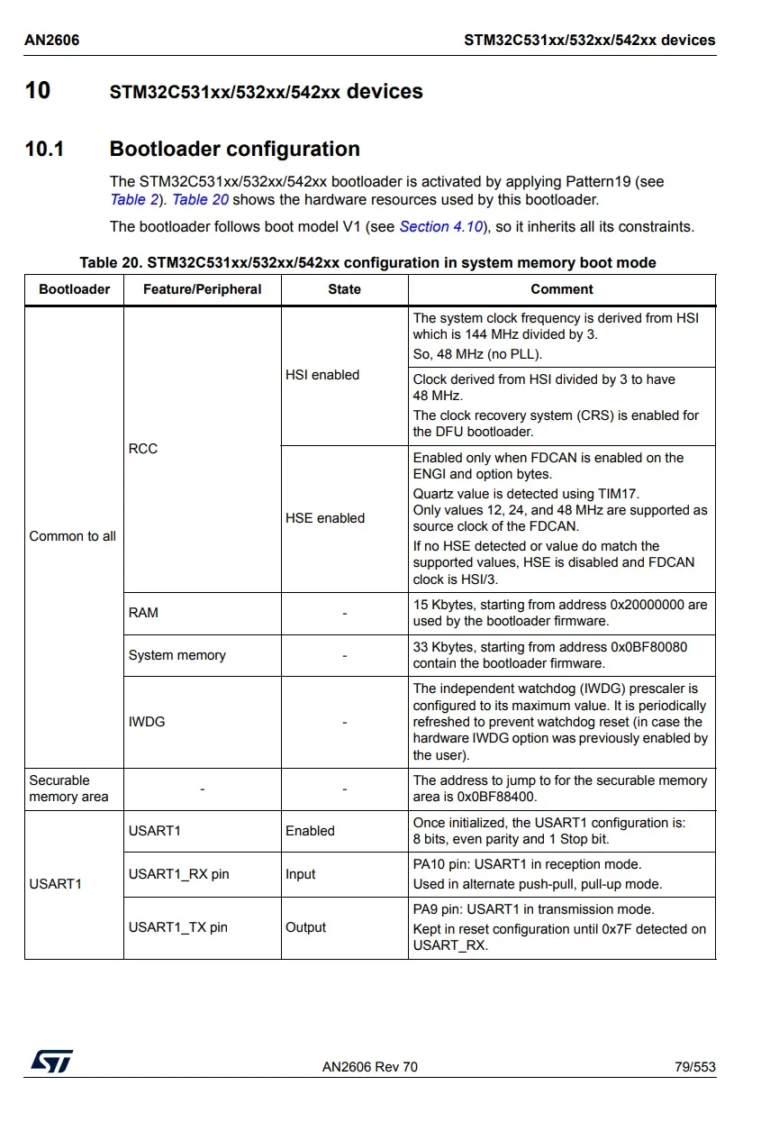
In the Boot Mode section of AN2606, ST describes the boot features and boot options for the STM32C542.
To enter the STM32C542 System Memory Bootloader via USART1, connect the following pins:
- PA9 → USART1_TX
- PA10 → USART1_RX
The UART communication parameters are:
- 8 data bits
- Even parity
- 1 stop bit
BOOT0 Configuration
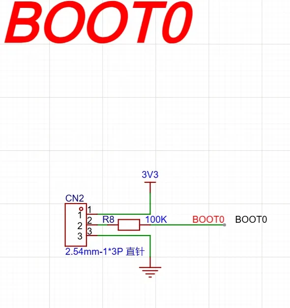
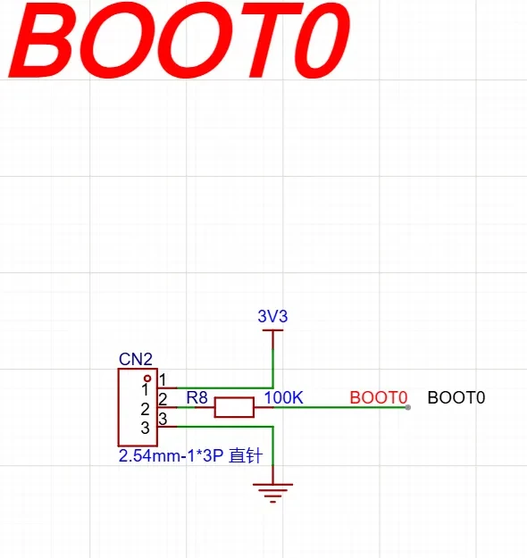
BOOT0 can be configured using the CN2 jumper cap.
Configuring BOOT_SEL
The STM32C5 BOOT_SEL Option Byte can be modified through software to determine whether the BOOT0 signal comes from the external BOOT0 pin or from the internal BOOT0 Option Bit.
The overall function flow is as follows:
Read the current BOOT_SEL configuration
↓
Determine whether modification is required
↓
Wait until the Flash is idle
↓
Clear error flags
↓
Unlock the Flash and Option Bytes
↓
Set the new BOOT_SEL value
↓
Start Option Bytes programming
↓
Wait for completion and check for errors
↓
Lock the Flash and Option Bytes again
↓
Reset the system to apply the new configuration
Configure_BOOT_SEL Code
#include "stm32c5xx_ll_flash.h"
#include <stdio.h>


/*
 * enable = 1:BOOT_SEL = 1,BOOT0 信号来自外部 BOOT0 引脚
 * enable = 0:BOOT_SEL = 0,BOOT0 信号来自内部 BOOT0 Option Bit
 */
static void Configure_BOOT_SEL(uint8_t enable)
{
    uint32_t target_boot_sel;
    uint32_t current_boot_sel;

    /*
     * STM32C5:
     * BOOT_SEL = 1: BOOT0 from BOOT0 pin
     * BOOT_SEL = 0: BOOT0 from BOOT0 option bit
     *
     * 当前头文件里有 LL_FLASH_OB_BOOT0_BOOTPIN,
     * 但没有 LL_FLASH_OB_BOOT0_BOOT0,所以 BOOT_SEL = 0 直接用 0U。
     */
    target_boot_sel = enable ? LL_FLASH_OB_BOOT0_BOOTPIN : 0U;

    current_boot_sel = LL_FLASH_OB_GetBoot0SourceSelection(FLASH);

    if (current_boot_sel == target_boot_sel)
    {
        printf("BOOT_SEL is already set to the desired value.\r\n");
        return;
    }

    /* 等待 Flash 空闲 */
    while ((FLASH->SR & FLASH_SR_BSY) != 0U)
    {
    }

    /*
     * 清除可能存在的 Option Byte 错误标志。
     * 如果不清除 OPTCHANGEERR,后面 OPTSTRT 可能无法启动。
     */
#ifdef FLASH_CCR_CLR_OPTCHANGEERR
    FLASH->CCR = FLASH_CCR_CLR_OPTCHANGEERR;
#endif

#ifdef FLASH_CCR_CLR_PGSERR
    FLASH->CCR = FLASH_CCR_CLR_PGSERR;
#endif

#ifdef FLASH_CCR_CLR_WRPERR
    FLASH->CCR = FLASH_CCR_CLR_WRPERR;
#endif

#ifdef FLASH_CCR_CLR_STRBERR
    FLASH->CCR = FLASH_CCR_CLR_STRBERR;
#endif

#ifdef FLASH_CCR_CLR_INCERR
    FLASH->CCR = FLASH_CCR_CLR_INCERR;
#endif

#ifdef FLASH_CCR_CLR_EOP
    FLASH->CCR = FLASH_CCR_CLR_EOP;
#endif

    /* 解锁 Flash */
    if (LL_FLASH_IsLocked(FLASH) != 0U)
    {
        LL_FLASH_SetUnlockKey(FLASH, LL_FLASH_KEY1);
        LL_FLASH_SetUnlockKey(FLASH, LL_FLASH_KEY2);
    }

    /* 解锁 Option Bytes */
    if (LL_FLASH_OB_IsLocked(FLASH) != 0U)
    {
        LL_FLASH_OB_SetUnlockKey(FLASH, LL_FLASH_OB_OPTKEY1);
        LL_FLASH_OB_SetUnlockKey(FLASH, LL_FLASH_OB_OPTKEY2);
    }

    if ((LL_FLASH_IsLocked(FLASH) != 0U) || (LL_FLASH_OB_IsLocked(FLASH) != 0U))
    {
        printf("Error: Failed to unlock FLASH or Option Bytes!\r\n");
        return;
    }

    /* 设置 BOOT_SEL */
    LL_FLASH_OB_SetBoot0SourceSelection(FLASH, target_boot_sel);

    /*
     * 启动 Option Bytes 修改。
     * RM0522 中说明:修改 FLASH_xxx_PRG 后,需要置位 OPTSTRT。
     */
    FLASH->OPTCR |= FLASH_OPTCR_OPTSTRT;

    /* 等待 Option Bytes 修改完成 */
    while ((FLASH->SR & FLASH_SR_BSY) != 0U)
    {
    }

    /* 检查是否发生 Option Byte 修改错误 */
    if ((FLASH->SR & FLASH_SR_OPTCHANGEERR) != 0U)
    {
        printf("Error: Option Bytes change failed!\r\n");

#ifdef FLASH_CCR_CLR_OPTCHANGEERR
        FLASH->CCR = FLASH_CCR_CLR_OPTCHANGEERR;
#endif
    }
    else
    {
        printf("BOOT_SEL configured successfully.\r\n");
    }

    /* 锁定 Option Bytes 和 Flash */
    LL_FLASH_OB_Lock(FLASH);
    LL_FLASH_Lock(FLASH);

    /*
     * 修改 Option Bytes 后建议复位,让配置重新加载。
     */
    NVIC_SystemReset();
}
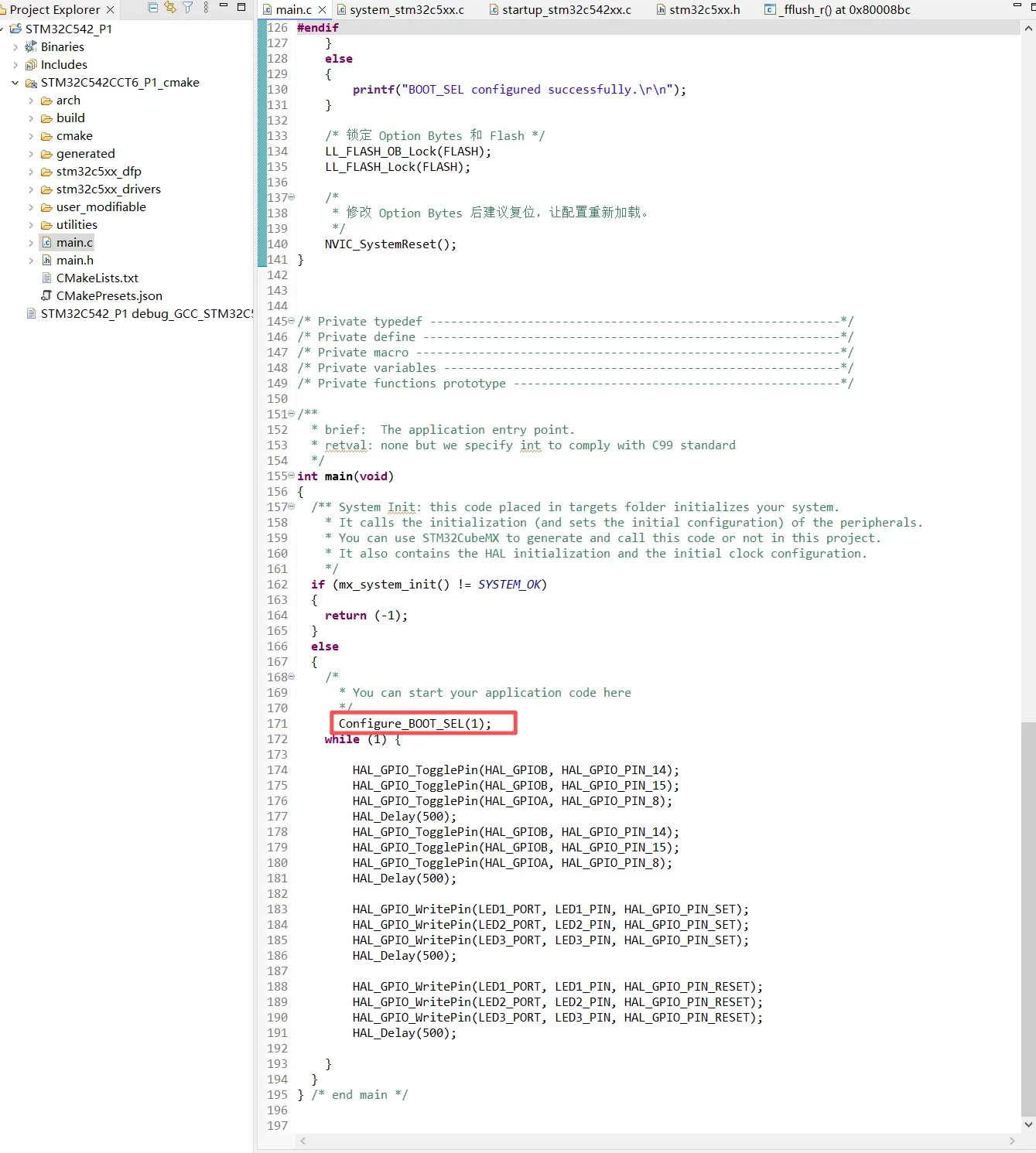
Then call the function once in main(). For example, if you want to configure the device to use the external BOOT0 pin:
Configure_BOOT_SEL(1);
If you want to configure the device to use the internal BOOT0 Option Bit:
Configure_BOOT_SEL(0);
Verify BOOT_SEL
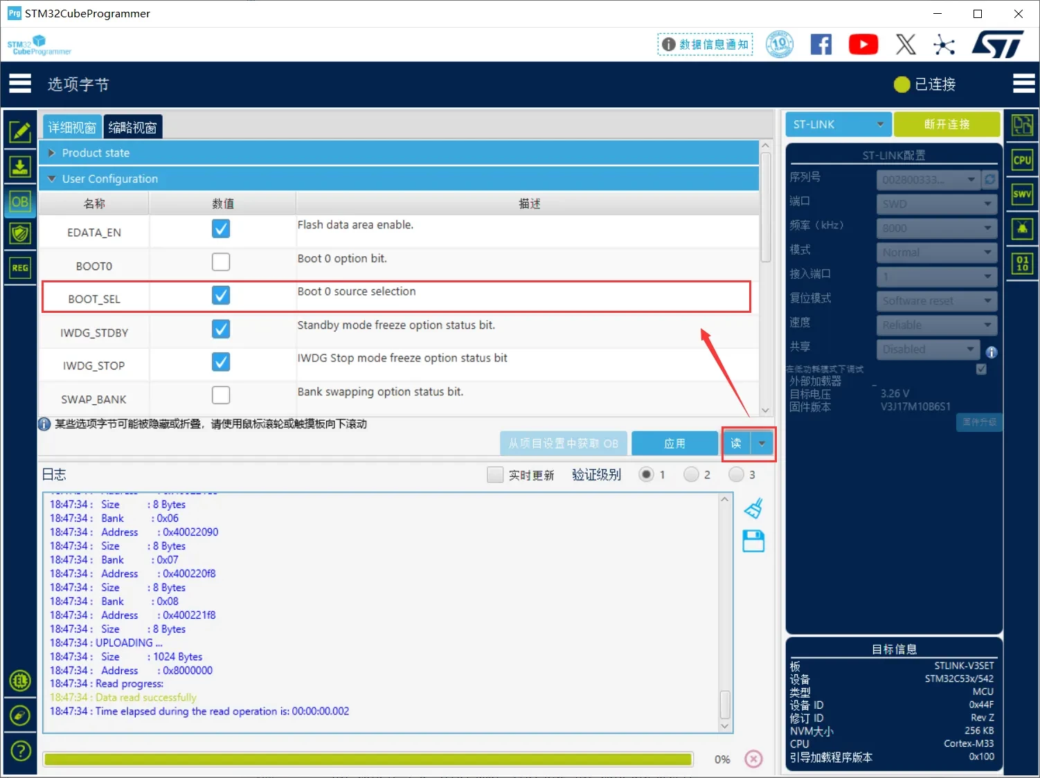
After configuring BOOT_SEL in software, the setting can be verified using STM32CubeProgrammer.
After calling Configure_BOOT_SEL(1) in the application, the MCU resets and reloads the updated Option Bytes. Then connect to the target board using STM32CubeProgrammer, navigate to Option Bytes → User Configuration, and click Read to retrieve the current Option Bytes configuration.
If BOOT_SEL is checked, the configuration has been successfully updated to 1, indicating that the BOOT0 signal is sourced from the external BOOT0 pin.
UART Programming
Connect BOOT0 to 3.3 V.
The BOOT0 level can be configured using the CN2 jumper cap.
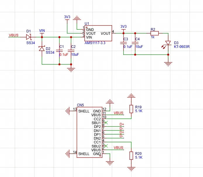
The onboard USB Type-C interface is connected to PA9 and PA10 through a CH340 USB-to-UART converter.
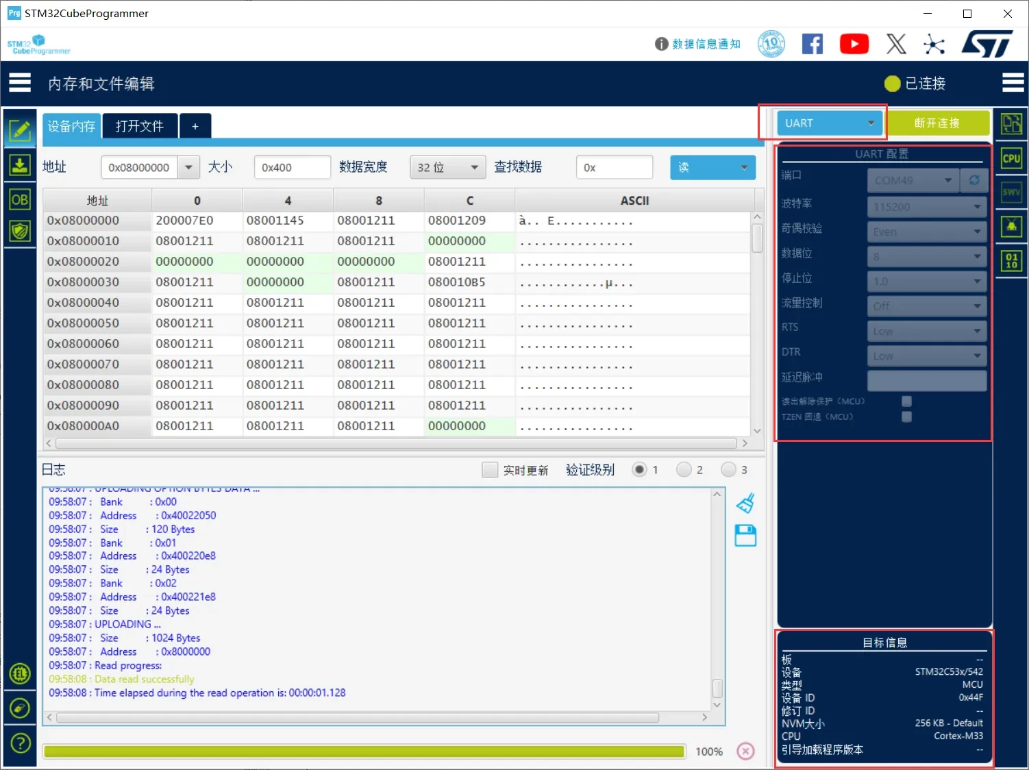
Open STM32CubeProgrammer and configure it for UART programming.
-
Select UART as the connection type to communicate with the STM32C5 System Memory Bootloader.
-
Configure the UART parameters: select the appropriate COM port, set the baud rate to 115200, Parity to Even, Data Bits to 8, and Stop Bits to 1.
-
In the Target Information panel, verify that the device is identified as STM32C53x/542, indicating that the Bootloader has successfully detected the target MCU.
-
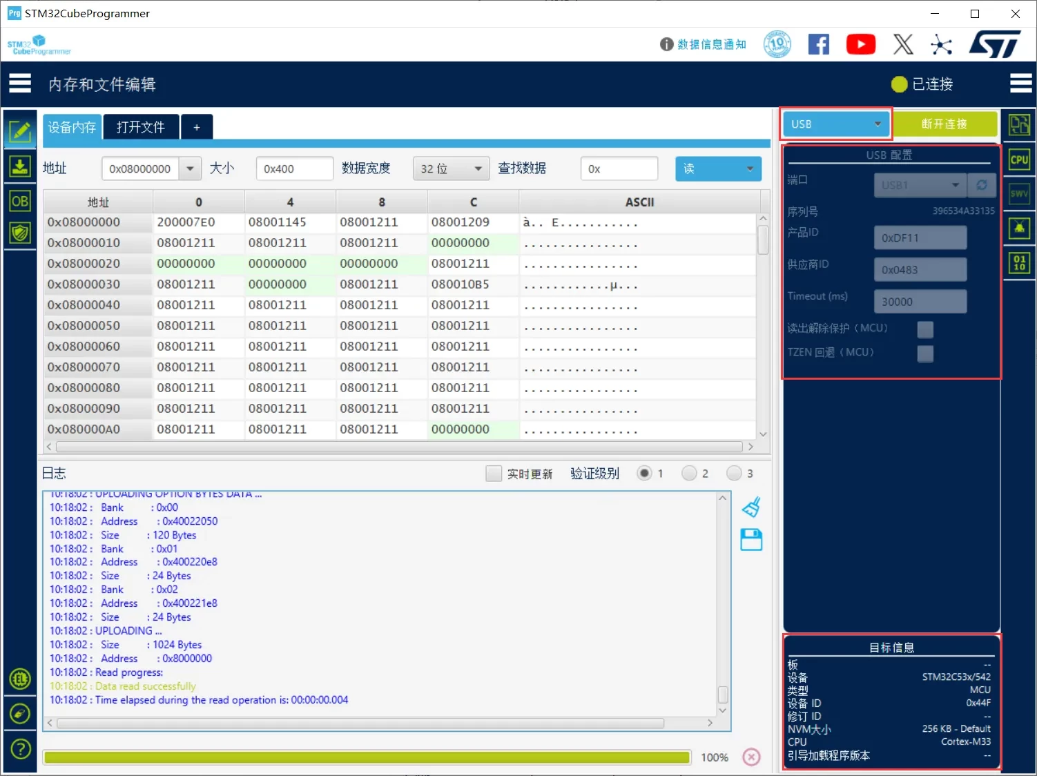
In the Memory window on the left, successfully reading data from address 0x08000000 with the log message "Data read successfully" confirms that communication with the UART Bootloader is working properly.
USB Programming
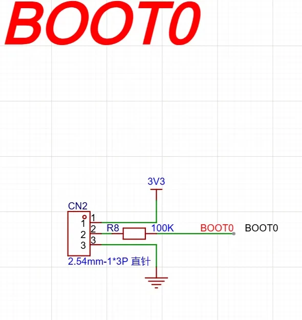
Connect BOOT0 to 3.3 V.
The BOOT0 level can be configured using the CN2 jumper cap.
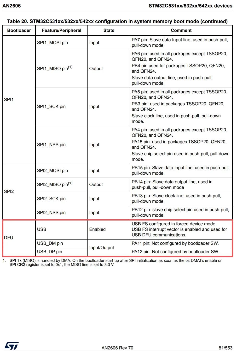
According to AN2606, the STM32C531xx, STM32C532xx, and STM32C542xx devices support the USB DFU Bootloader after entering the System Memory Bootloader. The USB_DM signal is mapped to PA11, and USB_DP is mapped to PA12.
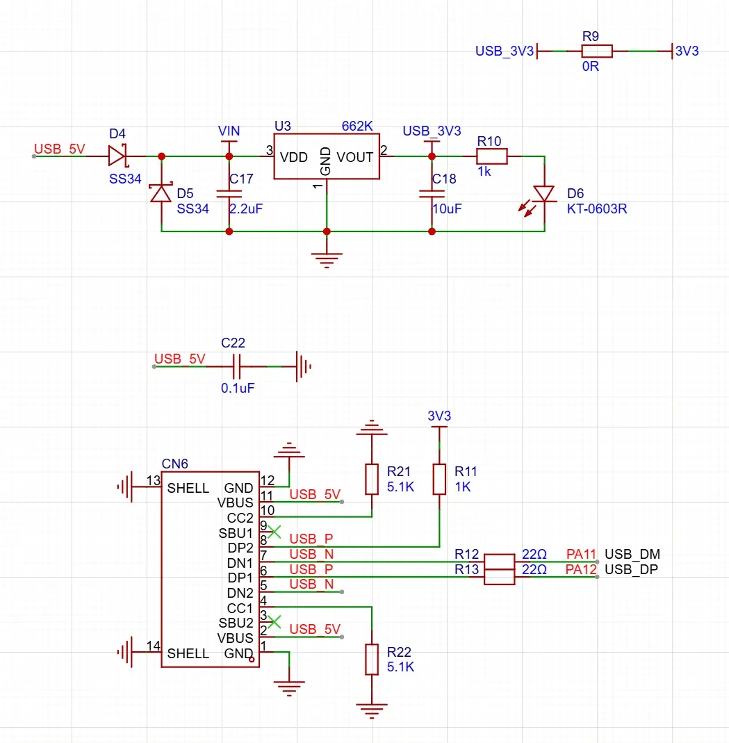
With a USB connector provided on the hardware, firmware can be downloaded via USB DFU using the USB connection mode in STM32CubeProgrammer.
The onboard USB Type-C connector is connected to PA11 and PA12 for USB DFU programming.
Connect to the STM32C5 System Memory Bootloader via USB DFU. After pulling BOOT0 high and resetting the MCU, select the USB interface in STM32CubeProgrammer. If the device is successfully detected as STM32C53x/542 and the Flash memory can be read, it confirms that the MCU has entered the System Memory Bootloader and that USB DFU communication is functioning correctly.