

STM32C542 Development (1) — Blinking an LED
Overview
The STM32C542 & SENSOR is an evaluation kit based on the STM32C5 series microcontroller. Built on ST's 40 nm process technology, the STM32C5 offers faster Flash access, higher performance, and lower power consumption.
The board also features a rich set of peripherals and interfaces, including dedicated connectors for the ST MEMS sensor (SENSOR) series, providing developers with a convenient and flexible platform for rapid prototyping and application development.
In this tutorial, we will perform a simple LED blinking test by configuring a GPIO pin as an output.
Hardware Preparation
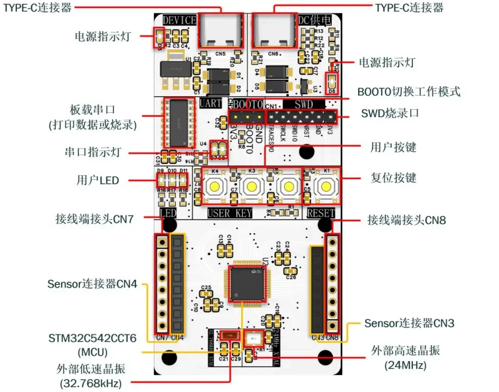
First, prepare an STM32C542 development board. In this tutorial, I will use a custom-designed development board. If you are interested in using the same board, feel free to contact me for samples.
Main MCU: STM32C542CCT6
Reference Project
The complete project source code is available on GitHub :
Creating a Project with STM32CubeMX 2
This tutorial uses STM32CubeMX 2 to generate the initialization code for the STM32C542CCT6.
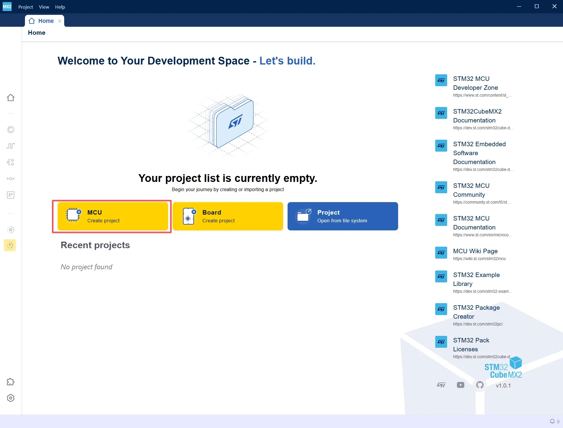
- Launch STM32CubeMX 2 and go to the Home page.
- Click MCU to create a new project based on the target device.
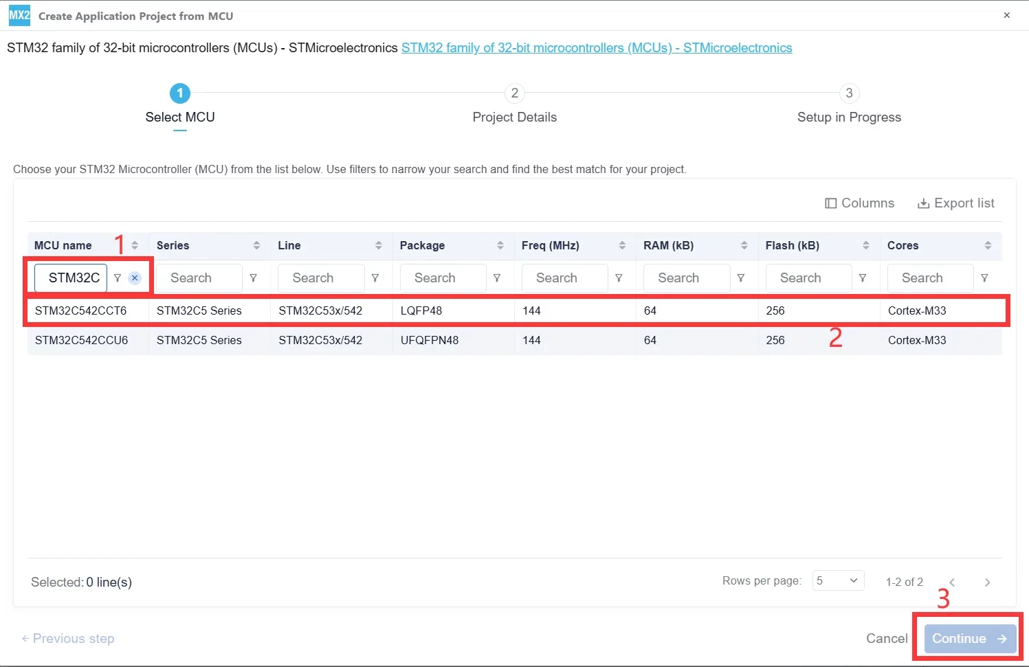
- Search for STM32C542CCT6 and select the device.
- Configure the required peripherals and GPIOs.
- Generate the project code for your preferred IDE (STM32CubeIDE is used in this tutorial).
In the MCU Name field, enter STM32C542CCT6. Select the corresponding STM32C5 device from the search results, then click Continue to proceed to the project configuration page.
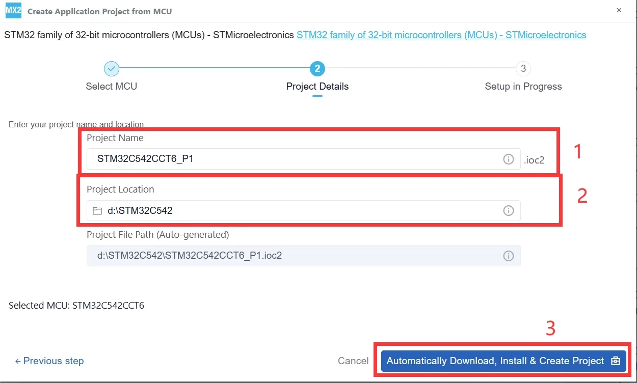
Enter the Project Name and select the Project Location. Then click Automatically Download, Install & Create Project. STM32CubeMX 2 will automatically download the required software package and generate the project.
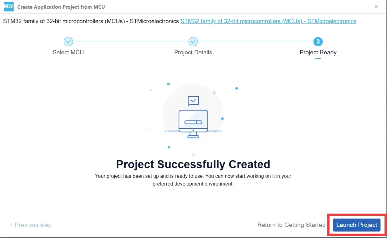
Once STM32CubeMX 2 displays "Project Successfully Created", click Launch Project in the lower-right corner to open the project configuration interface.
Clock Configuration
Configure the Clock Source
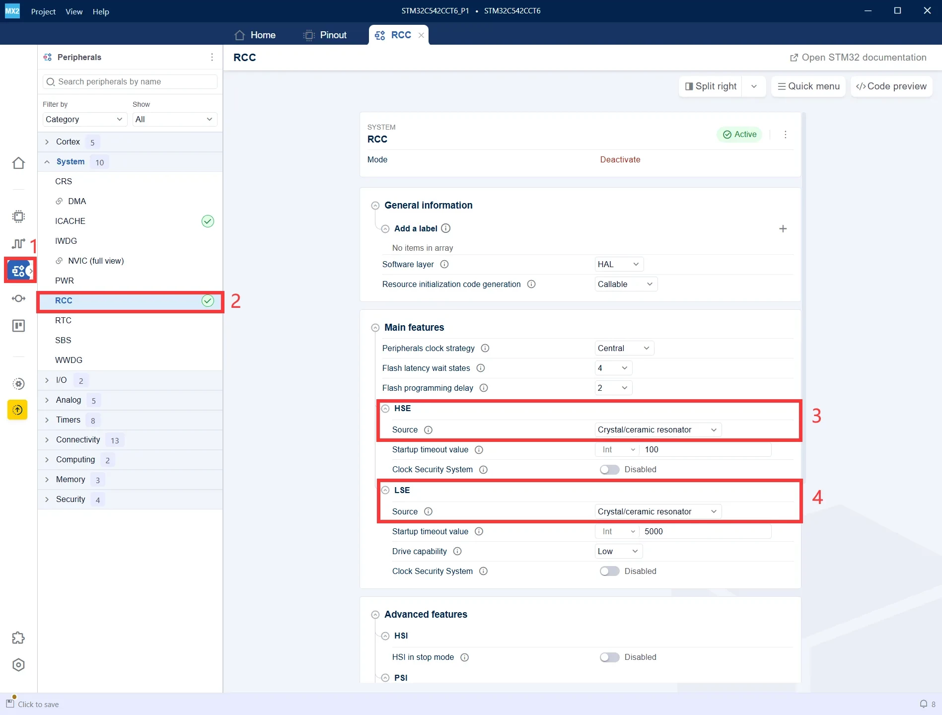
- Click Peripherals in the left navigation pane to open the peripheral configuration page.
- Under the System category, select RCC to configure the system clock source.
- Set HSE Source to Crystal/Ceramic Resonator to enable the external high-speed crystal oscillator.
- Set LSE Source to Crystal/Ceramic Resonator to enable the external low-speed crystal oscillator.
Configure the Clock Tree
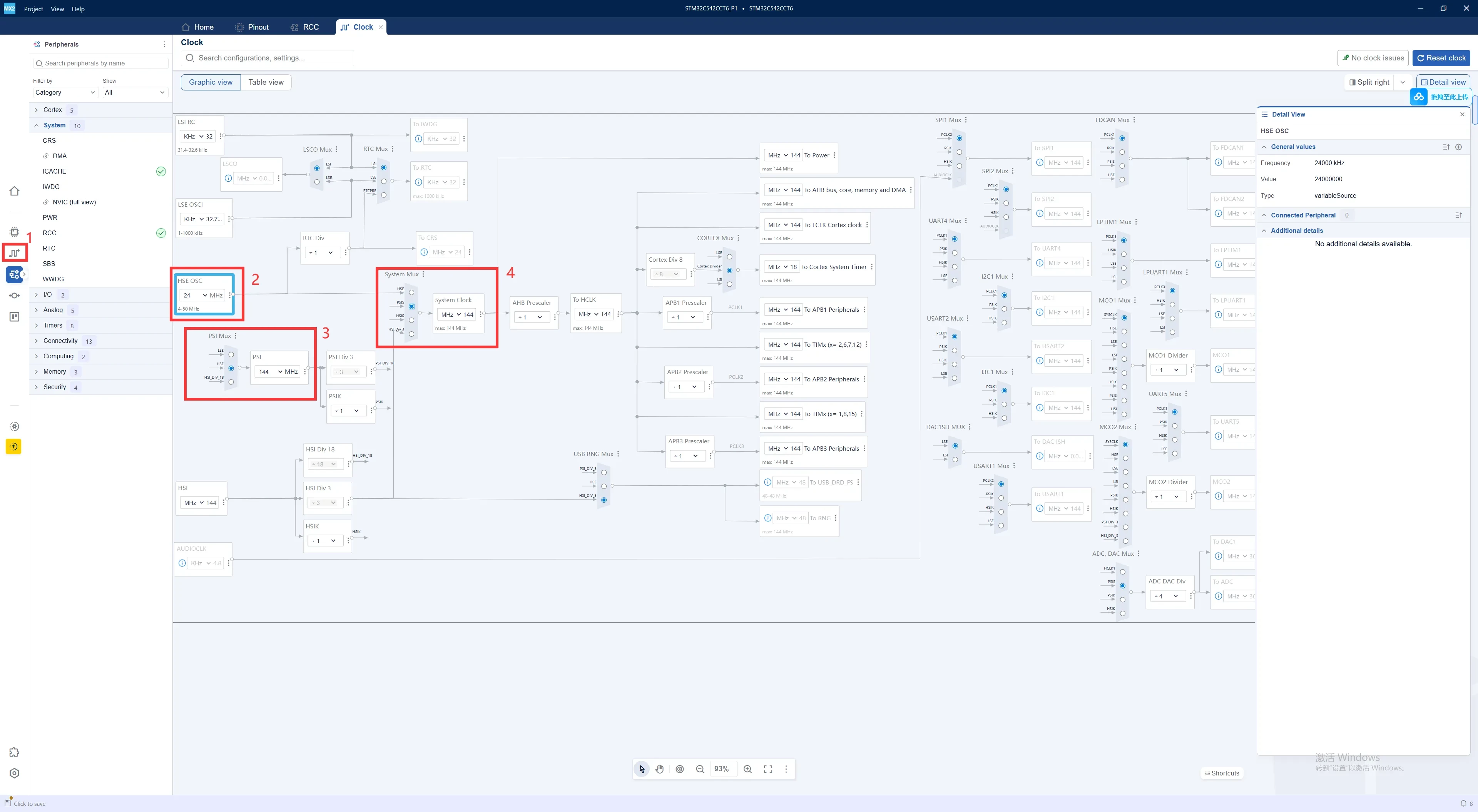
- Click the Clock Configuration (clock icon) in the left navigation pane to open the clock tree configuration page.
- Set HSE OSC to 24 MHz, which is the frequency of the external high-speed crystal.
- Configure PSI Mux and PLL to use the HSE clock as the PLL input and generate the desired system clock frequency.
- Set System Mux to use the PLL output as the system clock source. In this example, the SYSCLK is configured to run at 144 MHz.
Debug Configuration
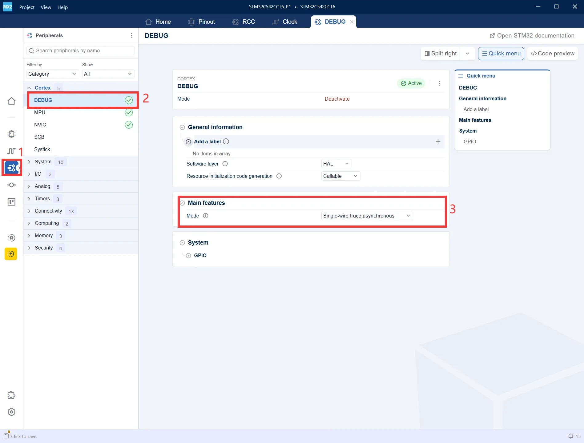
- In the Peripherals view, navigate to Cortex → DEBUG.
- Set Mode to Single-wire trace asynchronous.
- This configuration enables program downloading, online debugging, and SWV (Serial Wire Viewer) trace functionality.
LED Configuration
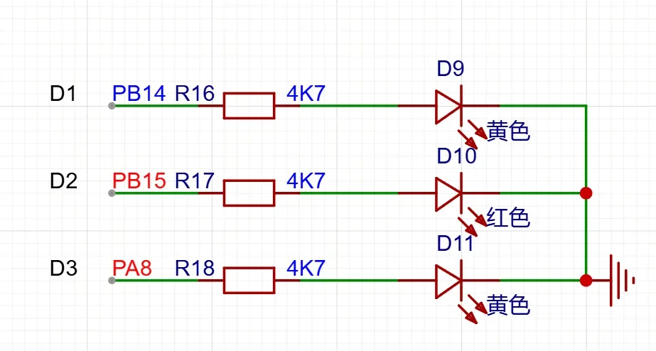
According to the schematic, the three onboard LEDs are connected to the following GPIO pins:
- LED1 → PA8
- LED2 → PB14
- LED3 → PB15
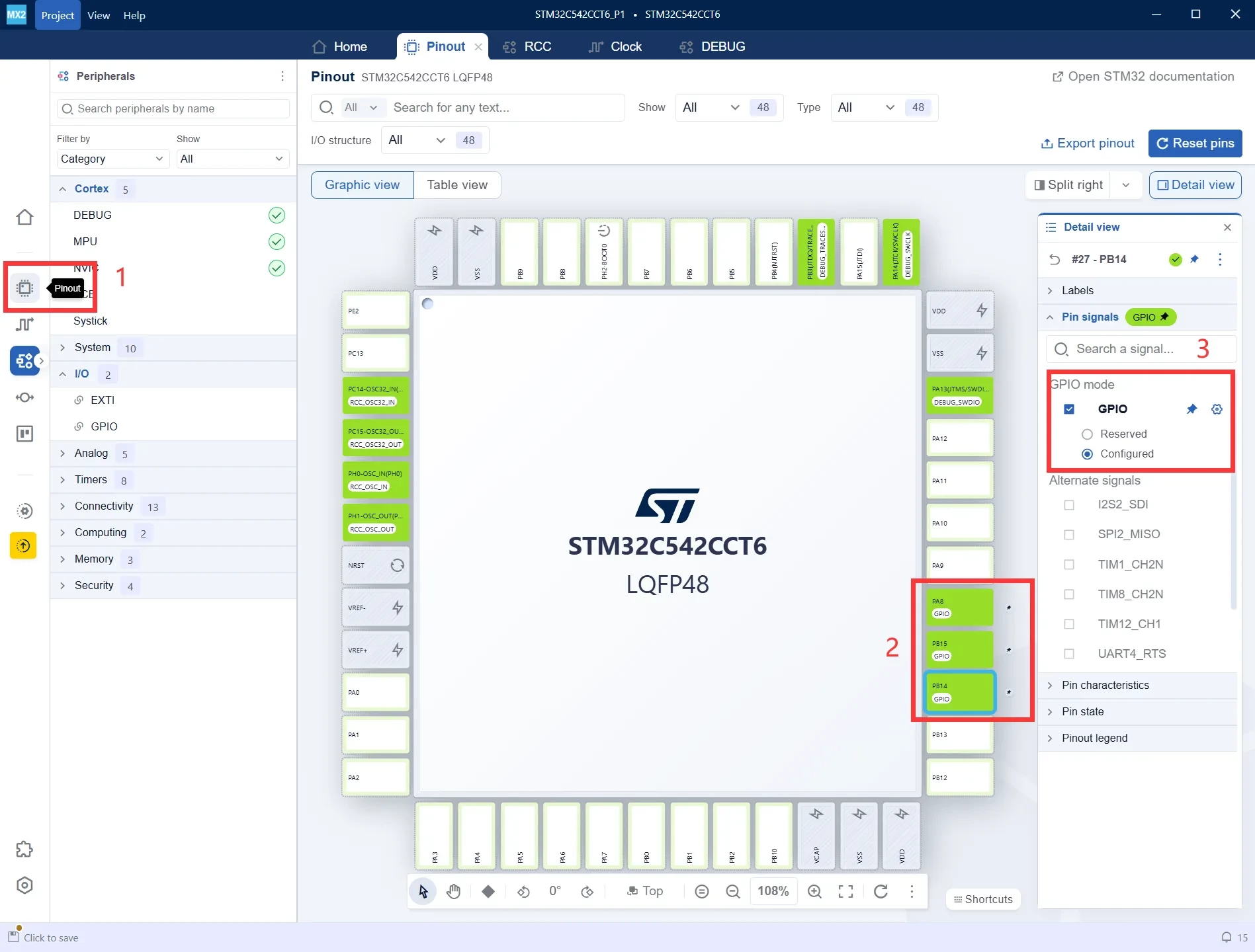
Configure PA8, PB14, and PB15 as GPIO_Output in STM32CubeMX 2.
1.Click the Pinout icon in the left navigation pane to open the pin configuration view.
2.According to the LED schematic, configure PA8, PB14, and PB15 as GPIO Output pins.
3.In the Pin Signals panel, select GPIO for each pin and verify that their status is shown as Configured.
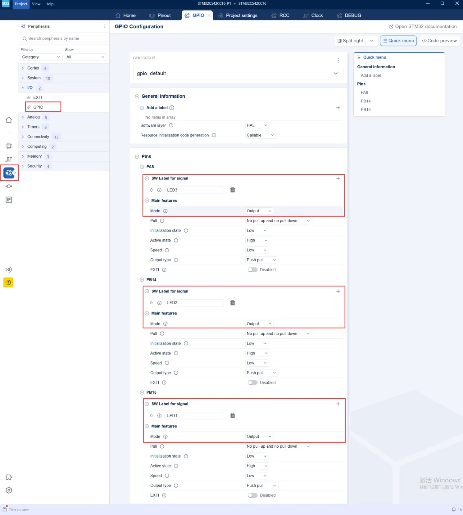
1.Open the Peripherals configuration page, then navigate to I/O → GPIO.
2.Expand the configuration for PA8, PB14, and PB15.
3.Assign an SW Label to each LED pin (for example, LED1, LED2, and LED3) and set the Mode to Output.
Generate the Project
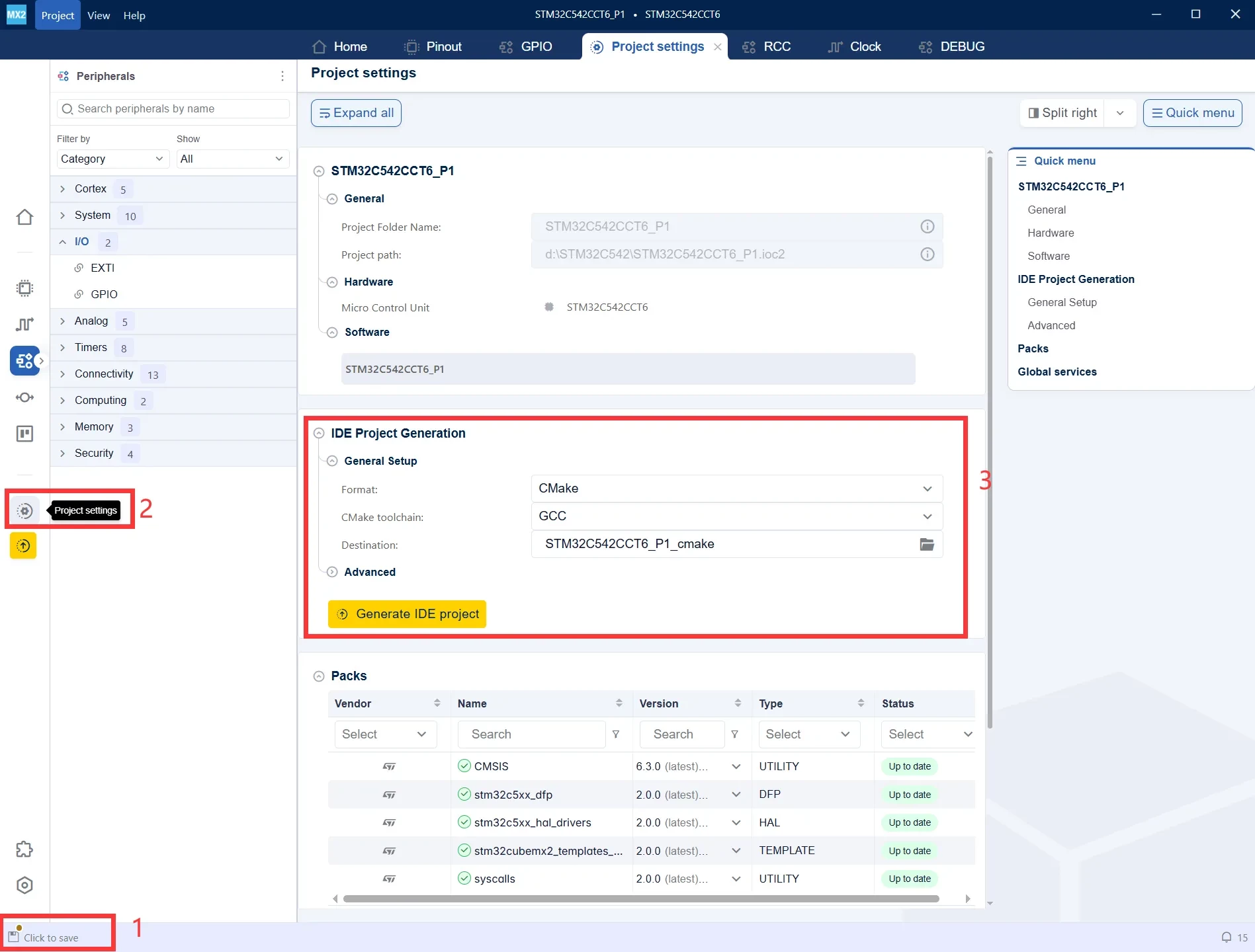
- After modifying the configuration, Click to save will appear in the lower-left corner. Save the current project configuration before generating the code.
- Click Project Settings in the left navigation pane to open the project generation settings.
- Under IDE Project Generation, select the desired project format and toolchain. In this tutorial, CMake + GCC is selected. Then click Generate IDE Project to generate the project.
Import the Project into STM32CubeIDE
- Launch STM32CubeIDE.
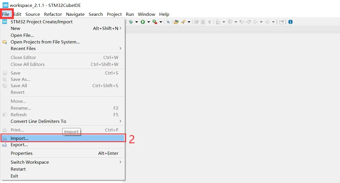
- From the menu bar, select File → Import... to import the CMake project generated by STM32CubeMX 2.
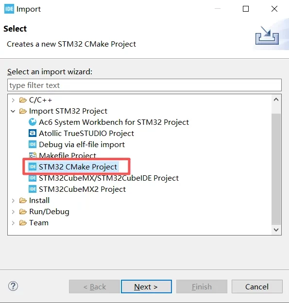
- In the Import dialog, expand Import STM32 Project.
- Select STM32 CMake Project.
- Click Next to proceed to the CMake project selection page.
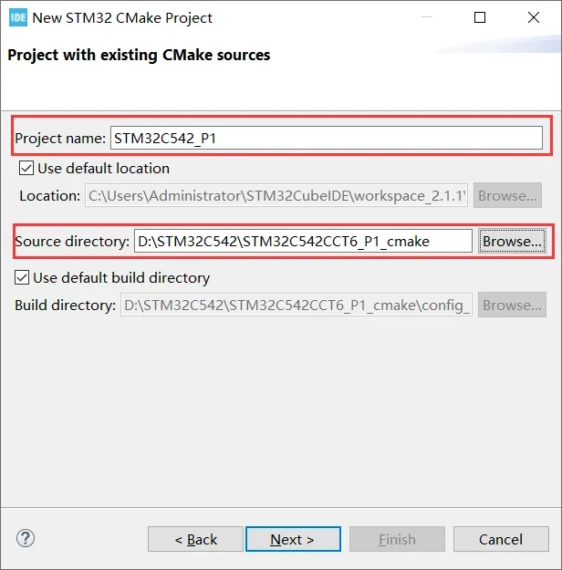
1.Enter the Project Name that will be displayed in STM32CubeIDE.
2.For Source Directory, browse to and select the CMake project directory generated by STM32CubeMX 2.
3.Click Next to continue with the project import.
-
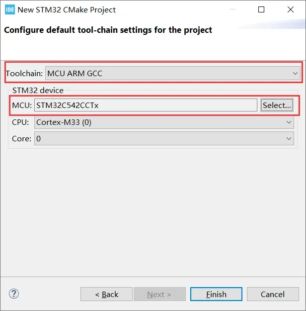
Toolchain: Select MCU ARM GCC, indicating that the project will be built using the ARM GCC toolchain.
-
MCU: Verify that the device is STM32C542CCTx, matching the MCU selected previously in STM32CubeMX 2.
-
CPU/Core: Confirm that the CPU is Cortex-M33 and the Core is 0.
-
Click Finish to complete the CMake project import.
Main Program
- Open the main.c file in the Project Explorer.
- Add the LED control code inside the while (1) main loop.
- Use HAL_GPIO_TogglePin() or HAL_GPIO_WritePin() to blink the LED.
- When the Console displays "Download verified successfully", the program has been successfully downloaded to the development board.
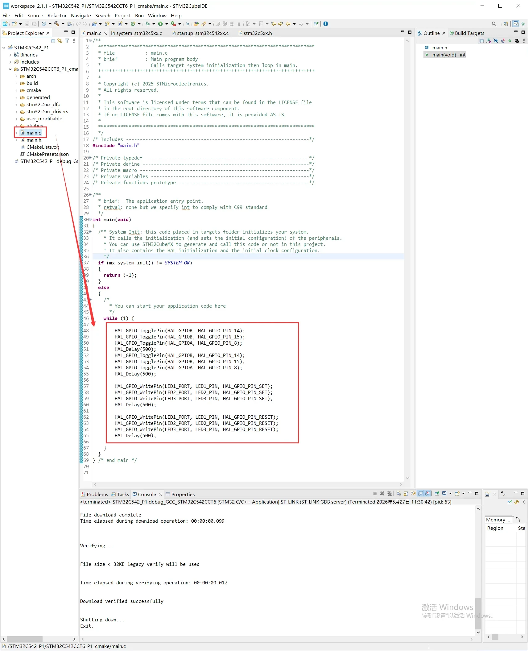
    while (1) {

    	HAL_GPIO_TogglePin(HAL_GPIOB, HAL_GPIO_PIN_14);
    	HAL_GPIO_TogglePin(HAL_GPIOB, HAL_GPIO_PIN_15);
    	HAL_GPIO_TogglePin(HAL_GPIOA, HAL_GPIO_PIN_8);
    	HAL_Delay(500);
    	HAL_GPIO_TogglePin(HAL_GPIOB, HAL_GPIO_PIN_14);
    	HAL_GPIO_TogglePin(HAL_GPIOB, HAL_GPIO_PIN_15);
    	HAL_GPIO_TogglePin(HAL_GPIOA, HAL_GPIO_PIN_8);
    	HAL_Delay(500);

        HAL_GPIO_WritePin(LED1_PORT, LED1_PIN, HAL_GPIO_PIN_SET);
        HAL_GPIO_WritePin(LED2_PORT, LED2_PIN, HAL_GPIO_PIN_SET);
        HAL_GPIO_WritePin(LED3_PORT, LED3_PIN, HAL_GPIO_PIN_SET);
        HAL_Delay(500);

        HAL_GPIO_WritePin(LED1_PORT, LED1_PIN, HAL_GPIO_PIN_RESET);
        HAL_GPIO_WritePin(LED2_PORT, LED2_PIN, HAL_GPIO_PIN_RESET);
        HAL_GPIO_WritePin(LED3_PORT, LED3_PIN, HAL_GPIO_PIN_RESET);
        HAL_Delay(500);

    }