We are planning to configure PWM generation on the NUCLEO-C542RC board using STM32CubeMX2. Could you please share the steps for configuring the PWM signal? An example project or configuration details would be very helpful.
There are several PWM modes available, but here is a general example of how to configure one of them in STM32CubeMX2.
Open your project and configure a timer instance for PWM output.
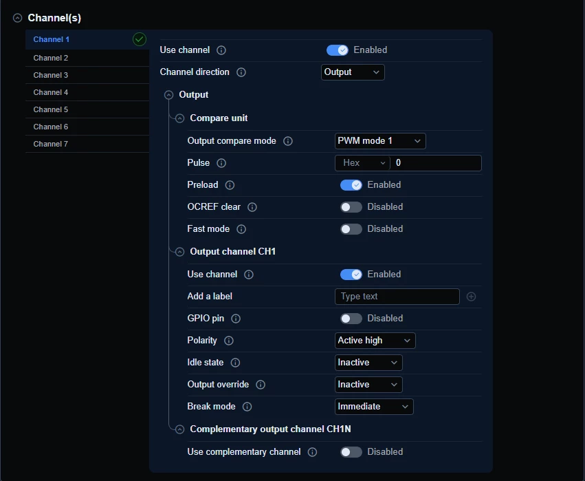
In the timer channel configuration:
Enable one channel as an output channel
Select a PWM mode
Set the output polarity as needed
Enable preload if required
Example channel configuration
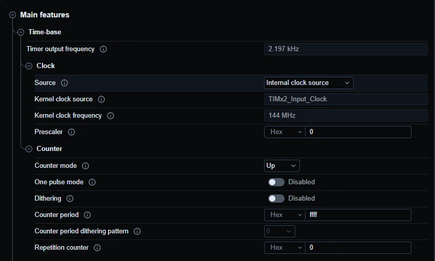
Configure the timer base settings according to the PWM frequency you want:
Select the internal clock source
Choose the counter mode
Set the prescaler and period values to obtain the desired PWM frequency
Set the repetition counter if needed
Example Timer Base configuration
In the pinout view, assign the corresponding timer channel to the desired pin and keep it in alternate-function mode.
To adjust the duty cycle, update the channel compare value within the timer period range:
Minimum value for 0%
Mid-range value for around 50%
Maximum value for nearly 100%
If DMA updates are needed, configure a DMA channel for the timer compare event, with memory-to-peripheral direction, memory increment enabled, and peripheral address fixed, then link it to the timer channel.
Generate the code, initialize the timer in the application, and start the PWM output using the generated HAL timer handle.
This results in a PWM output configured on the selected timer channel and pin, with optional DMA support for updating the duty cycle dynamically.
There are several PWM modes available, but here is a general example of how to configure one of them in STM32CubeMX2.
Open your project and configure a timer instance for PWM output.
In the timer channel configuration:
Enable one channel as an output channel
Select a PWM mode
Set the output polarity as needed
Enable preload if required
Example channel configuration
Configure the timer base settings according to the PWM frequency you want:
Select the internal clock source
Choose the counter mode
Set the prescaler and period values to obtain the desired PWM frequency
Set the repetition counter if needed
Example Timer Base configuration
In the pinout view, assign the corresponding timer channel to the desired pin and keep it in alternate-function mode.
To adjust the duty cycle, update the channel compare value within the timer period range:
Minimum value for 0%
Mid-range value for around 50%
Maximum value for nearly 100%
If DMA updates are needed, configure a DMA channel for the timer compare event, with memory-to-peripheral direction, memory increment enabled, and peripheral address fixed, then link it to the timer channel.
Generate the code, initialize the timer in the application, and start the PWM output using the generated HAL timer handle.
This results in a PWM output configured on the selected timer channel and pin, with optional DMA support for updating the duty cycle dynamically.
Kind regards,
DHIF Khaled
"Please mark my answer as best by clicking on the “Accept as solution"" button if it fully answered your question. This will help other users find this solution faster."