Trouble using alternate function on STM32C092
Hi,
i'm missing something in the configuration of alternate function on STM32C092.
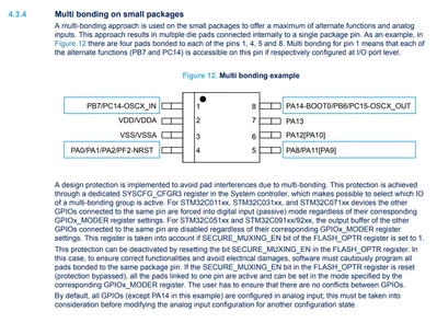
I can't get working alternare function on shared pin, interested physical pin are PIN 1, 15, 20.
Example1:
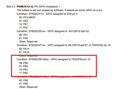
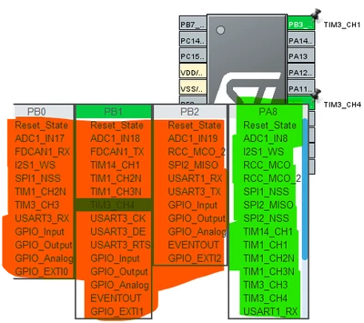
PIN15 only the function on PA8 are working properly, neither (PB0,PB1 or PB2) are working at all with any function even a simple toggle. I'm pretty sure that the Alternate Function property are being generated correctly.
Example2:
PIN20 Generating a PWM with TIM3_CH1 only works on PB6, if the same timer is passed to PB4 i can't get any output.
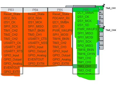
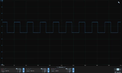
Same on PIN1 i can get output only on PB7.
There is the HAL_TIM_MspPostInit where PB6 is working as expected but PB1 isn't:
void HAL_TIM_MspPostInit(TIM_HandleTypeDef* htim)
{
 GPIO_InitTypeDef GPIO_InitStruct = {0};
 if(htim->Instance==TIM3)
 {
 /* USER CODE BEGIN TIM3_MspPostInit 0 */

 /* USER CODE END TIM3_MspPostInit 0 */

 __HAL_RCC_GPIOB_CLK_ENABLE();
 /**TIM3 GPIO Configuration
 PB1 ------> TIM3_CH4
 PB6 ------> TIM3_CH1
 */
 GPIO_InitStruct.Pin = GPIO_PIN_1;
 GPIO_InitStruct.Mode = GPIO_MODE_AF_PP;
 GPIO_InitStruct.Pull = GPIO_NOPULL;
 GPIO_InitStruct.Speed = GPIO_SPEED_FREQ_LOW;
 GPIO_InitStruct.Alternate = GPIO_AF1_TIM3;
 HAL_GPIO_Init(GPIOB, &GPIO_InitStruct);

 GPIO_InitStruct.Pin = GPIO_PIN_6;
 GPIO_InitStruct.Mode = GPIO_MODE_AF_PP;
 GPIO_InitStruct.Pull = GPIO_NOPULL;
 GPIO_InitStruct.Speed = GPIO_SPEED_FREQ_LOW;
 GPIO_InitStruct.Alternate = GPIO_AF12_TIM3;
 HAL_GPIO_Init(GPIOB, &GPIO_InitStruct);

 /* USER CODE BEGIN TIM3_MspPostInit 1 */

 /* USER CODE END TIM3_MspPostInit 1 */
 }

}
Register after init:
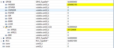
TIM3 Init:
static void MX_TIM3_Init(void)
{

 /* USER CODE BEGIN TIM3_Init 0 */

 /* USER CODE END TIM3_Init 0 */

 TIM_ClockConfigTypeDef sClockSourceConfig = {0};
 TIM_MasterConfigTypeDef sMasterConfig = {0};
 TIM_OC_InitTypeDef sConfigOC = {0};

 /* USER CODE BEGIN TIM3_Init 1 */

 /* USER CODE END TIM3_Init 1 */
 htim3.Instance = TIM3;
 htim3.Init.Prescaler = 6000;
 htim3.Init.CounterMode = TIM_COUNTERMODE_UP;
 htim3.Init.Period = 10;
 htim3.Init.ClockDivision = TIM_CLOCKDIVISION_DIV1;
 htim3.Init.AutoReloadPreload = TIM_AUTORELOAD_PRELOAD_ENABLE;
 if (HAL_TIM_Base_Init(&htim3) != HAL_OK)
 {
 Error_Handler();
 }
 sClockSourceConfig.ClockSource = TIM_CLOCKSOURCE_INTERNAL;
 if (HAL_TIM_ConfigClockSource(&htim3, &sClockSourceConfig) != HAL_OK)
 {
 Error_Handler();
 }
 if (HAL_TIM_PWM_Init(&htim3) != HAL_OK)
 {
 Error_Handler();
 }
 sMasterConfig.MasterOutputTrigger = TIM_TRGO_RESET;
 sMasterConfig.MasterSlaveMode = TIM_MASTERSLAVEMODE_DISABLE;
 if (HAL_TIMEx_MasterConfigSynchronization(&htim3, &sMasterConfig) != HAL_OK)
 {
 Error_Handler();
 }
 sConfigOC.OCMode = TIM_OCMODE_PWM1;
 sConfigOC.Pulse = 5;
 sConfigOC.OCPolarity = TIM_OCPOLARITY_HIGH;
 sConfigOC.OCFastMode = TIM_OCFAST_DISABLE;
 if (HAL_TIM_PWM_ConfigChannel(&htim3, &sConfigOC, TIM_CHANNEL_1) != HAL_OK)
 {
 Error_Handler();
 }
 if (HAL_TIM_PWM_ConfigChannel(&htim3, &sConfigOC, TIM_CHANNEL_4) != HAL_OK)
 {
 Error_Handler();
 }
 /* USER CODE BEGIN TIM3_Init 2 */

 /* USER CODE END TIM3_Init 2 */
 HAL_TIM_MspPostInit(&htim3);

}
On the hardware side i have already cutted off any component that can interfere.
Did someone have some clue?
Useful info:
MCU : STM32C092FCP6 TSSOP20
CubeMX Ver. 6.15.0-RC7
CubeIDE Ver: 1.14.0
Thank you.