Visitor
June 20, 2026
Question

STM32F401RET Simulink ADC Signal Issues

  • June 20, 2026
  • 1 reply
  • 7 views
I am using an STM32F401RET with the Simulink STM32 support package.
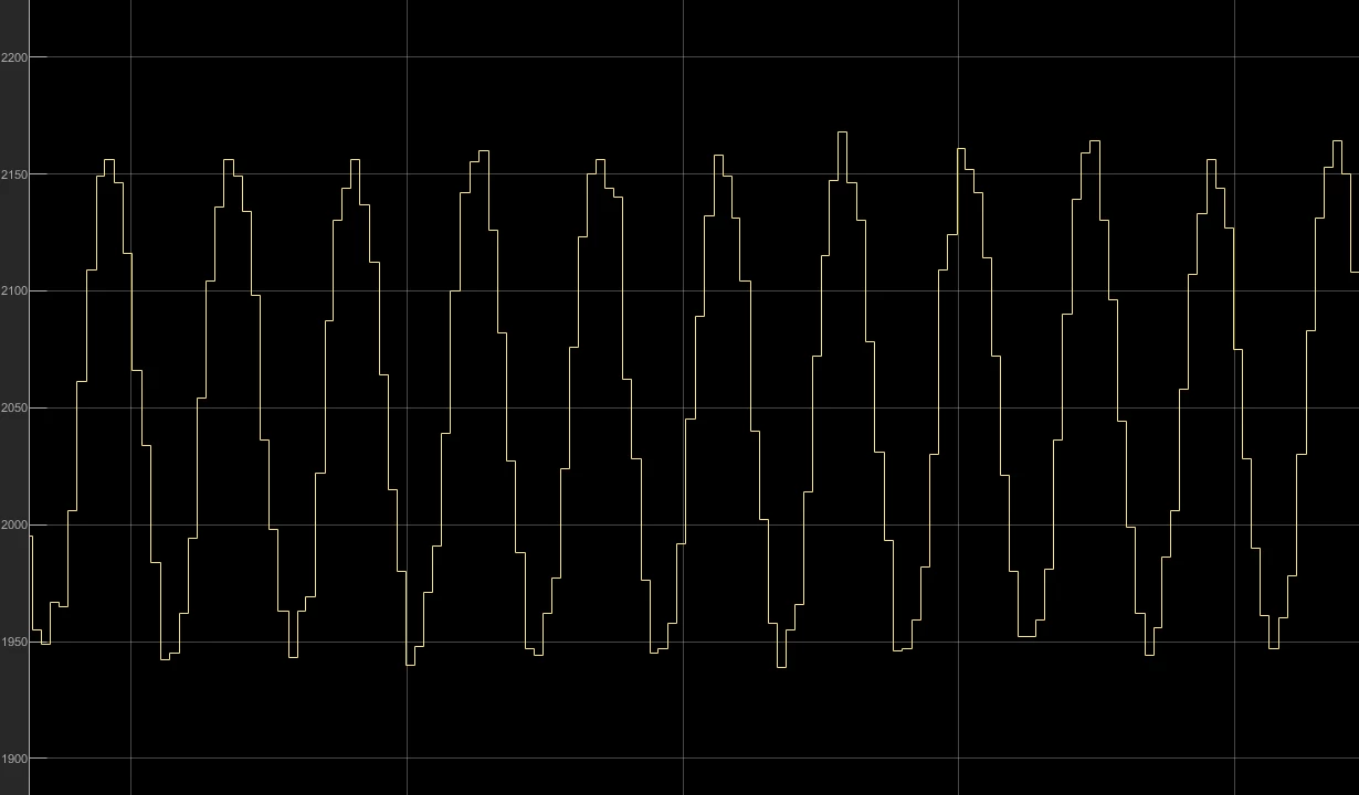
My problem is that I am measuring a pure sine wave from a voltage sensor. I verified the sensor output using an oscilloscope, and the waveform is clean. However, the ADC readings on the STM32 show a very low-quality signal that appears as a stepped waveform rather than a smooth sine wave.
I have already tried increasing the sampling rate, running the ADC at its maximum clock speed, and using a timer as an external trigger source for the ADC, but none of these solutions improved the result.
I would appreciate any suggestions on what could be causing this issue.


1 reply

mƎALLEm
ST Technical Moderator
June 20, 2026

Hello ​@WAHEED and welcome to the ST community,

This most probably -as you said- an issue of the sampling time. What signal frequency you are measuring on that input? what sampling frequency you set to measure that signal?

Unfortunately we cannot help you on that as you are using Simulink. For Matlab/Simulink environment related questions please ask them in the Mathworks community.

Perhaps, use HAL driver te community can help you.

To give better visibility on the answered topics, please click "Best answer" on the reply which solved your issue or answered your question.