


Start PWM with DMA (HAL_TIM_PWM_Start_DMA) results in Hardfault
Hello,
I want to create a simple PWM with changing duty cycle. To do so, I have created a PWM with fixed frequency. With the DMA, I change pulses which will result in a modification of duty cycle.
To create something clean, I have configured STM32CubeMX and generated fresh files (configuration in attached documents below).
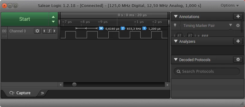
If I test my PWM with fixed frequency and fixed duty cycle, everything is working (without DMA). I have not modified files, just added this line to start the PWM:
HAL_TIM_PWM_Start(&htim4, TIM_CHANNEL_4);Result as expected:
Now I want to do the same thing with the DMA. So I have created a buffer with 2 arrays, with my 2 pulses. And I use it like that:
uint32_t buffer[2] = {42, 21}; // 42 is 50% duty cycle for my config, 21 is 25%
[...]
// At the end of timer4 init
HAL_TIM_PWM_Start_DMA(&htim4, TIM_CHANNEL_4, buffer, 2);
[...]
And here is the problem:
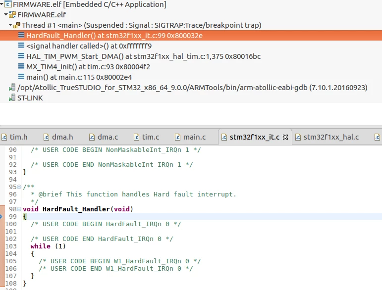
More particularly, it seems to crash at this moment:
/* Set the DMA error callback */
htim->hdma[TIM_DMA_ID_CC4]->XferErrorCallback = TIM_DMAError ;
Maybe I am missing to do something...
Any help would be appreciated. Thanks!
More information: I am using a stm32f103. As you can see in attached files, the last release of stm32CubeMx and the last version of F1 library : V1.7.0
I have looked carefully to provided examples (TIM_DMA, etc...) and I always reach the same result.
Quick access to some parts of the code:
main.c :
int main(void)
{
 /* MCU Configuration--------------------------------------------------------*/

 /* Reset of all peripherals, Initializes the Flash interface and the Systick. */
 HAL_Init();

 /* Configure the system clock */
 SystemClock_Config();

 /* Initialize all configured peripherals */
 MX_GPIO_Init();
 MX_DMA_Init();
 MX_USB_PCD_Init();
 MX_TIM4_Init();

 /* Infinite loop */
 while (1)
 {
 }
}
time.c:
uint32_t buffer[2] = {42, 21};

TIM_HandleTypeDef htim4;
DMA_HandleTypeDef hdma_tim4_up;

/* TIM4 init function */
void MX_TIM4_Init(void)
{
 TIM_ClockConfigTypeDef sClockSourceConfig = {0};
 TIM_MasterConfigTypeDef sMasterConfig = {0};
 TIM_OC_InitTypeDef sConfigOC = {0};

 htim4.Instance = TIM4;
 htim4.Init.Prescaler = 0;
 htim4.Init.CounterMode = TIM_COUNTERMODE_UP;
 htim4.Init.Period = 84;
 htim4.Init.ClockDivision = TIM_CLOCKDIVISION_DIV1;
 htim4.Init.AutoReloadPreload = TIM_AUTORELOAD_PRELOAD_ENABLE;
 if (HAL_TIM_Base_Init(&htim4) != HAL_OK)
 {
 Error_Handler();
 }
 sClockSourceConfig.ClockSource = TIM_CLOCKSOURCE_INTERNAL;
 if (HAL_TIM_ConfigClockSource(&htim4, &sClockSourceConfig) != HAL_OK)
 {
 Error_Handler();
 }
 if (HAL_TIM_PWM_Init(&htim4) != HAL_OK)
 {
 Error_Handler();
 }
 sMasterConfig.MasterOutputTrigger = TIM_TRGO_RESET;
 sMasterConfig.MasterSlaveMode = TIM_MASTERSLAVEMODE_DISABLE;
 if (HAL_TIMEx_MasterConfigSynchronization(&htim4, &sMasterConfig) != HAL_OK)
 {
 Error_Handler();
 }
 sConfigOC.OCMode = TIM_OCMODE_PWM1;
 sConfigOC.Pulse = 42;
 sConfigOC.OCPolarity = TIM_OCPOLARITY_HIGH;
 sConfigOC.OCFastMode = TIM_OCFAST_DISABLE;
 if (HAL_TIM_PWM_ConfigChannel(&htim4, &sConfigOC, TIM_CHANNEL_4) != HAL_OK)
 {
 Error_Handler();
 }
 HAL_TIM_MspPostInit(&htim4);

 //HAL_TIM_PWM_Start(&htim4, TIM_CHANNEL_4);
 HAL_TIM_PWM_Start_DMA(&htim4, TIM_CHANNEL_4, buffer, 2);

}

void HAL_TIM_Base_MspInit(TIM_HandleTypeDef* tim_baseHandle)
{

 if(tim_baseHandle->Instance==TIM4)
 {
 /* TIM4 clock enable */
 __HAL_RCC_TIM4_CLK_ENABLE();

 /* TIM4 DMA Init */
 /* TIM4_UP Init */
 hdma_tim4_up.Instance = DMA1_Channel7;
 hdma_tim4_up.Init.Direction = DMA_MEMORY_TO_PERIPH;
 hdma_tim4_up.Init.PeriphInc = DMA_PINC_DISABLE;
 hdma_tim4_up.Init.MemInc = DMA_MINC_ENABLE;
 hdma_tim4_up.Init.PeriphDataAlignment = DMA_PDATAALIGN_HALFWORD;
 hdma_tim4_up.Init.MemDataAlignment = DMA_MDATAALIGN_HALFWORD;
 hdma_tim4_up.Init.Mode = DMA_NORMAL;
 hdma_tim4_up.Init.Priority = DMA_PRIORITY_VERY_HIGH;
 if (HAL_DMA_Init(&hdma_tim4_up) != HAL_OK)
 {
 Error_Handler();
 }

 __HAL_LINKDMA(tim_baseHandle,hdma[TIM_DMA_ID_UPDATE],hdma_tim4_up);
 }
}
void HAL_TIM_MspPostInit(TIM_HandleTypeDef* timHandle)
{

 GPIO_InitTypeDef GPIO_InitStruct = {0};
 if(timHandle->Instance==TIM4)
 {
 __HAL_RCC_GPIOB_CLK_ENABLE();
 /**TIM4 GPIO Configuration
 PB9 ------> TIM4_CH4
 */
 GPIO_InitStruct.Pin = GPIO_PIN_9;
 GPIO_InitStruct.Mode = GPIO_MODE_AF_PP;
 GPIO_InitStruct.Speed = GPIO_SPEED_FREQ_HIGH;
 HAL_GPIO_Init(GPIOB, &GPIO_InitStruct);
 }

}
dma.c
void MX_DMA_Init(void)
{
 /* DMA controller clock enable */
 __HAL_RCC_DMA1_CLK_ENABLE();

 /* DMA interrupt init */
 /* DMA1_Channel7_IRQn interrupt configuration */
 HAL_NVIC_SetPriority(DMA1_Channel7_IRQn, 0, 0);
 HAL_NVIC_EnableIRQ(DMA1_Channel7_IRQn);

}
stm32f1xx_it.c
void DMA1_Channel7_IRQHandler(void)
{
 HAL_DMA_IRQHandler(&hdma_tim4_up);
}