

New SDRAM model does not work with STM32F7 (but old one does)
I've migrated to a new custom board, which uses a STM32F746IE and a new SDRAM model, NDS36PT5-20ET by Insignis. And although I could make a MT48LC16M16A2 by Micron work in the previous board, I have no luck with the Insignis SDRAM.
The Insignis SDRAM is rated for 200 MHz. I'm using a system clock of 200 MHz, so the SDRAM is clocked at 100 MHz. Based on the timings in the datasheet, I configured CubeMX like this:
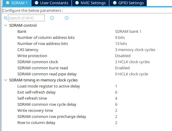 Each FMC cycle is 10 ns, so I divided the datasheet time by 10 ns and rounded up. The Write recovery time would be 1 cycle, but CubeMX sets this to 2. I also chose a CL of 3, since the datasheet doesn't list any Clock cycle time for CL 2.
Similarly, I initialize the SDRAM with this function in main():
static void SDRAM_Init()
{
 FMC_SDRAM_CommandTypeDef Command;

 __IO uint32_t tmpmrd =0;
 /* Step 3: Configure a clock configuration enable command */
 Command.CommandMode = FMC_SDRAM_CMD_CLK_ENABLE;
 Command.CommandTarget = FMC_SDRAM_CMD_TARGET_BANK1;
 Command.AutoRefreshNumber = 1;
 Command.ModeRegisterDefinition = 0;
 HAL_SDRAM_SendCommand(&hsdram1, &Command, SDRAM_TIMEOUT);

 /* Step 4: Insert 100 us minimum delay */
 /* Inserted delay is equal to 1 ms due to systick time base unit (ms) */
 HAL_Delay(1);

 /* Step 5: Configure a PALL (precharge all) command */
 Command.CommandMode = FMC_SDRAM_CMD_PALL;
 Command.CommandTarget = FMC_SDRAM_CMD_TARGET_BANK1;
 Command.AutoRefreshNumber = 1;
 Command.ModeRegisterDefinition = 0;
 HAL_SDRAM_SendCommand(&hsdram1, &Command, SDRAM_TIMEOUT);

 /* Step 6 : Configure a Auto-Refresh command */
 Command.CommandMode = FMC_SDRAM_CMD_AUTOREFRESH_MODE;
 Command.CommandTarget = FMC_SDRAM_CMD_TARGET_BANK1;
 Command.AutoRefreshNumber = 2; // Insignis SDRAM
 Command.ModeRegisterDefinition = 0;
 HAL_SDRAM_SendCommand(&hsdram1, &Command, SDRAM_TIMEOUT);

 /* Step 7: Program the external memory mode register */
 tmpmrd = (uint32_t)SDRAM_MODEREG_BURST_LENGTH_1 |
 SDRAM_MODEREG_BURST_TYPE_SEQUENTIAL |
 SDRAM_MODEREG_CAS_LATENCY_3 |
 //SDRAM_MODEREG_CAS_LATENCY_2 |
 SDRAM_MODEREG_OPERATING_MODE_STANDARD |
 SDRAM_MODEREG_WRITEBURST_MODE_SINGLE;

 Command.CommandMode = FMC_SDRAM_CMD_LOAD_MODE;
 Command.CommandTarget = FMC_SDRAM_CMD_TARGET_BANK1;
 Command.AutoRefreshNumber = 1;
 Command.ModeRegisterDefinition = tmpmrd;
 HAL_SDRAM_SendCommand(&hsdram1, &Command, SDRAM_TIMEOUT);

 /* Step 8: Set the refresh rate counter: (64 ms / 8192 x Freq) - 20 */
 hsdram1.Instance->SDRTR |= ((uint32_t)761); // 2HCLK, Insignis SDRAM, 100 MHz
}
My quick and dirty test program
uint32_t i;
 for (i = 0; i < 16384; i += 2) {
 *(__IO uint16_t *) (SDRAM_BASE + i) = i & 0xffff;
 }

 for (i = 0; i < 16384; i += 2) {
 uint16_t data = *(__IO uint16_t *) (SDRAM_BASE + i);
 if (data != (i & 0xffff)) {
 while (1); // breakpoint here
 }
 }
shows an error when reading the first value: 0x3ffe instead of 0 (and that consistently).
To rule out any layout errors, I used the Insignis SDRAM in the older board, in which I got the Micron SDRAM to work. The Insignis still would not run with the old board (same error as in the new board).
For either board, what could be wrong with my configuration above?
