

F405 USB HID Clock Configuration
I'm trying to get a custom F405 board (open hardware from stm32duino) to run a simple HID example (https://notes.iopush.net/stm32-custom-usb-hid-step-by-step-2/). I got it running on an F103 and am trying to get it running on the F405, but it doesn't connect (neither when debugging via SWD, nor when not debugging and simply connecting the the PC).
From what I see, it remains in the "USBD_STATE_SUSPENDED" state.
Trying to figure out the differences, I noticed the Clock configuration screen between the F103 and F405 is different, and as such also the generated code.
The F103 has these settings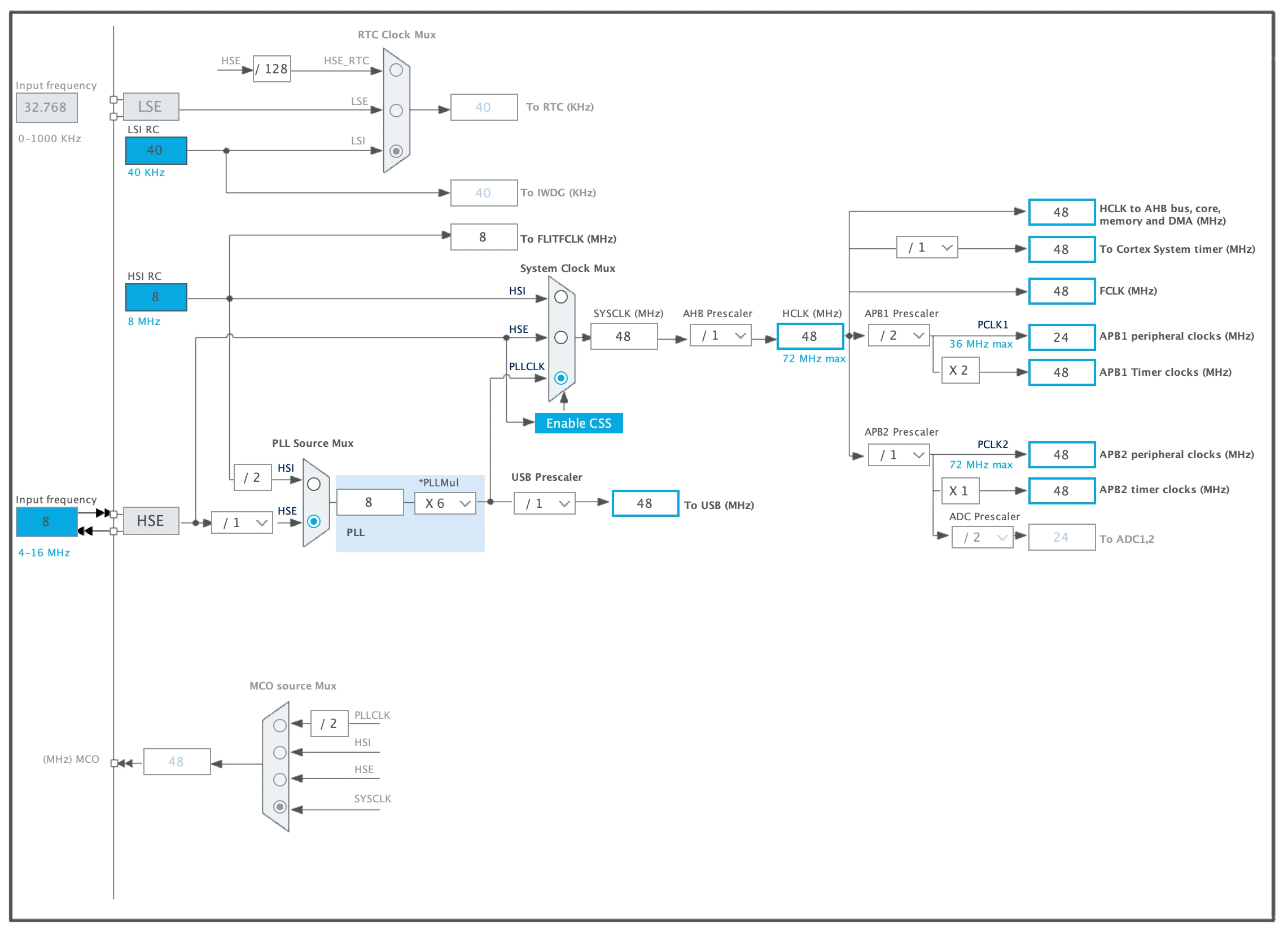
which generates code like this:
void SystemClock_Config(void)
{
 RCC_OscInitTypeDef RCC_OscInitStruct = {0};
 RCC_ClkInitTypeDef RCC_ClkInitStruct = {0};
 RCC_PeriphCLKInitTypeDef PeriphClkInit = {0};

 /** Initializes the CPU, AHB and APB busses clocks
 */
 RCC_OscInitStruct.OscillatorType = RCC_OSCILLATORTYPE_HSE;
 RCC_OscInitStruct.HSEState = RCC_HSE_ON;
 RCC_OscInitStruct.HSEPredivValue = RCC_HSE_PREDIV_DIV1;
 RCC_OscInitStruct.HSIState = RCC_HSI_ON;
 RCC_OscInitStruct.PLL.PLLState = RCC_PLL_ON;
 RCC_OscInitStruct.PLL.PLLSource = RCC_PLLSOURCE_HSE;
 RCC_OscInitStruct.PLL.PLLMUL = RCC_PLL_MUL6;
 if (HAL_RCC_OscConfig(&RCC_OscInitStruct) != HAL_OK)
 {
 Error_Handler();
 }
 /** Initializes the CPU, AHB and APB busses clocks
 */
 RCC_ClkInitStruct.ClockType = RCC_CLOCKTYPE_HCLK|RCC_CLOCKTYPE_SYSCLK
 |RCC_CLOCKTYPE_PCLK1|RCC_CLOCKTYPE_PCLK2;
 RCC_ClkInitStruct.SYSCLKSource = RCC_SYSCLKSOURCE_PLLCLK;
 RCC_ClkInitStruct.AHBCLKDivider = RCC_SYSCLK_DIV1;
 RCC_ClkInitStruct.APB1CLKDivider = RCC_HCLK_DIV2;
 RCC_ClkInitStruct.APB2CLKDivider = RCC_HCLK_DIV1;

 if (HAL_RCC_ClockConfig(&RCC_ClkInitStruct, FLASH_LATENCY_1) != HAL_OK)
 {
 Error_Handler();
 }
 PeriphClkInit.PeriphClockSelection = RCC_PERIPHCLK_USB;
 PeriphClkInit.UsbClockSelection = RCC_USBCLKSOURCE_PLL;
 if (HAL_RCCEx_PeriphCLKConfig(&PeriphClkInit) != HAL_OK)
 {
 Error_Handler();
 }
}
The F405 clock looks like this
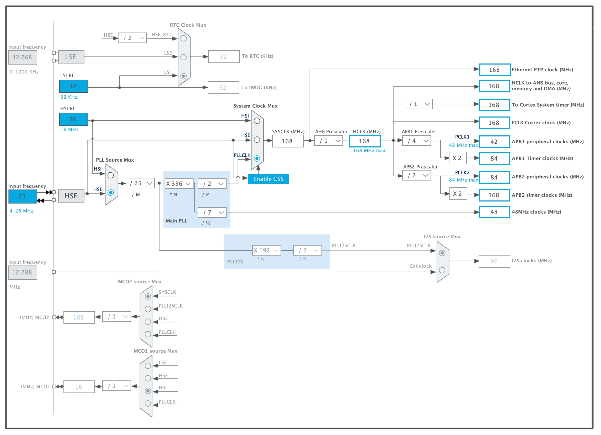
and the generated code looks like this:
void SystemClock_Config(void)
{
 RCC_OscInitTypeDef RCC_OscInitStruct = {0};
 RCC_ClkInitTypeDef RCC_ClkInitStruct = {0};

 /** Configure the main internal regulator output voltage
 */
 __HAL_RCC_PWR_CLK_ENABLE();
 __HAL_PWR_VOLTAGESCALING_CONFIG(PWR_REGULATOR_VOLTAGE_SCALE1);
 /** Initializes the CPU, AHB and APB busses clocks
 */
 RCC_OscInitStruct.OscillatorType = RCC_OSCILLATORTYPE_HSE;
 RCC_OscInitStruct.HSEState = RCC_HSE_ON;
 RCC_OscInitStruct.PLL.PLLState = RCC_PLL_ON;
 RCC_OscInitStruct.PLL.PLLSource = RCC_PLLSOURCE_HSE;
 RCC_OscInitStruct.PLL.PLLM = 25;
 RCC_OscInitStruct.PLL.PLLN = 336;
 RCC_OscInitStruct.PLL.PLLP = RCC_PLLP_DIV2;
 RCC_OscInitStruct.PLL.PLLQ = 7;
 if (HAL_RCC_OscConfig(&RCC_OscInitStruct) != HAL_OK)
 {
 Error_Handler();
 }
 /** Initializes the CPU, AHB and APB busses clocks
 */
 RCC_ClkInitStruct.ClockType = RCC_CLOCKTYPE_HCLK|RCC_CLOCKTYPE_SYSCLK
 |RCC_CLOCKTYPE_PCLK1|RCC_CLOCKTYPE_PCLK2;
 RCC_ClkInitStruct.SYSCLKSource = RCC_SYSCLKSOURCE_PLLCLK;
 RCC_ClkInitStruct.AHBCLKDivider = RCC_SYSCLK_DIV1;
 RCC_ClkInitStruct.APB1CLKDivider = RCC_HCLK_DIV4;
 RCC_ClkInitStruct.APB2CLKDivider = RCC_HCLK_DIV2;

 if (HAL_RCC_ClockConfig(&RCC_ClkInitStruct, FLASH_LATENCY_5) != HAL_OK)
 {
 Error_Handler();
 }
}
So where the F103 does something with a "peripheral usb clock" there is no such thing for the F405? There doesn't seem to be anything "usb" related in the F405 clock configuration screen... Does it use the "Main PLL -> 48 Mhz Clock (Mhz) (the one at the bottom)?
Looking at the MCU example pack for the F4, at an F413ZH (because it doesn't have samples for the F405), there's also some code to initialise Peripheral/USB, like this:
 /* Select PLLSAI output as USB clock source */
 PeriphClkInitStruct.PLLI2S.PLLI2SM = 8;
 PeriphClkInitStruct.PLLI2S.PLLI2SQ = 4;
 PeriphClkInitStruct.PLLI2S.PLLI2SN = 192;
 PeriphClkInitStruct.PeriphClockSelection = RCC_PERIPHCLK_CK48;
 PeriphClkInitStruct.Clk48ClockSelection = RCC_CK48CLKSOURCE_PLLI2SQ;
 HAL_RCCEx_PeriphCLKConfig(&PeriphClkInitStruct);
I still found this in the STM32F405xx manual: (2.2.31) "The USB OTG full-speed controller requires a dedicated 48 MHz clock that is generated by a PLL connected to the HSE oscillator. ".
So why isn't there anything like that generated for the F405? How do I get CubeIDE to generate such code for the F405? Or is it correct as-is ( I doubt it, but maybe...? )
