


F334R8 - CubeMX - HRTIM1 setup for multiple complementary high resolution PWM signals
Hi,
I have a project using an H7 which is handling multiple tasks. One of them is to generate 3 pairs of PWM signals through TIM1. Everything is working fine, however I am not satisfied with the level of control I have on the system and I am looking at increasing the resolution of the PWM duty cycles.
I first though of using the HRTIM built into the H7 but sadly, it would only double my resolution (basically from 0-5000 to 0-10000).
So I ordered an F334R8 which has a DLL on top of its already decent HRTIM1.
I am not discarding the H7 which I need for other tasks, so I will connecting both the H7 and the F334R8 through SPI (Eventually, they will be on the same PCB with short traces). I have good experience with SPI and feels like this will do the job fine.
So I am looking at configuring the HRTIM1 on the F334R8 for 3 pairs of complementary PWM signals. These drive a DRV8301 3phase driver.
Again I have everything working fine with the H7, however I am struggling a little with the HRTIM configuration on the F334. The H7 on TIM1 had a little more intuitive approach with setup, so I need some guidance.
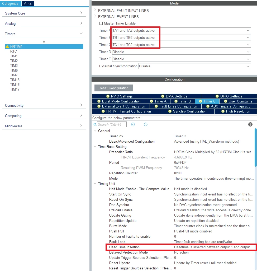
The screenshot above shows what I have done so far. It shows Timer C here, but I have the same settings for Timers A and B as well.
I am bit confused as to why I cannot put a value greater than 0xFFDF on the period.
Is the period similar to the ARR register on non HR timers? On regular timers, what you do is your duty cycle between 0 and the ARR value. Is this the same here? In other words does the Period Value represent the maximum value for the duty cycle?
I have set a dead time insertion between the output 1 and 2 so that output 2 is fully function of output 1. Is this the right way to generate complimentary signals?
I feel like it is missing something. Again looking at the setup on TIM1, you typically select "PWM Generation CH1 CH1N" which is sufficient to make CH1 and CH1N complimentary.
Anyway scrolling down the outputs configuration here's how I set them up:
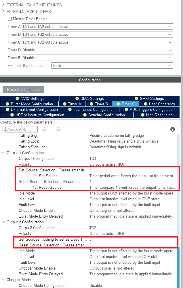
Here I set the Set/Reset sources for output 1 and left them to 0 for output 2.
I haven't touched the polarity and idle mode/levels. Is this correct though?
I'll receive the nucleo F334R8 tomorrow, so worst case scenario I'll have to run through some trial and errors, but it would be nice to actually understand/learn from people who've done something similar with this HRTIM1.
Cheers