

Question
CubeMX Generates different FSMC pinout then BSP for STM3240G-EVAL
Posted on January 20, 2016 at 17:01
 Pinout generated from STM32CubeMX:
Hello,
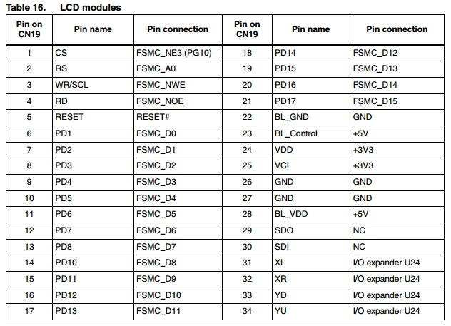
I am attempting to use the STM32CubeMX to generate a base project for the STM3240G-EVAL, specifically attempting to use the evaluations boards LCD. However when I enable the FSMC in CubeMX and configure it, the pins it assigns are in a different order then what the BSP and demonstration firmware use. I am unable to modify the arrangement of the pins, effectively making the code CubeMX generates useless. I have also tried enabling ''Initialize all IP with their default Mode'' when selecting the STM3240G-EVAL in the board selector and get the same pinout. Is there a way to change the assigned FSMC pins with CubeMX, or is this a bug in the definition file for the board that can be resolved? Pinout from STM3240G-EVAL Spec Sheet for LCD:
Pinout generated from STM32CubeMX:
/** FSMC GPIO Configuration
PE3 ------> FSMC_A19
PE1 ------> FSMC_NBL1
PE0 ------> FSMC_NBL0
PD7 ------> FSMC_NE1
PE4 ------> FSMC_A20
PB7 ------> FSMC_NL
PG10 ------> FSMC_NE3
PD6 ------> FSMC_NWAIT
PD0 ------> FSMC_D2
PG9 ------> FSMC_NE2
PD5 ------> FSMC_NWE
PD1 ------> FSMC_D3
PD4 ------> FSMC_NOE
PD3 ------> FSMC_CLK
PF0 ------> FSMC_A0
PF2 ------> FSMC_A2
PF1 ------> FSMC_A1
PF3 ------> FSMC_A3
PF4 ------> FSMC_A4
PF5 ------> FSMC_A5
PG5 ------> FSMC_A15
PG4 ------> FSMC_A14
PG3 ------> FSMC_A13
PD15 ------> FSMC_D1
PG2 ------> FSMC_A12
PG1 ------> FSMC_A11
PD14 ------> FSMC_D0
PD13 ------> FSMC_A18
PF13 ------> FSMC_A7
PG0 ------> FSMC_A10
PE13 ------> FSMC_D10
PD12 ------> FSMC_A17
PD11 ------> FSMC_A16
PD10 ------> FSMC_D15
PF12 ------> FSMC_A6
PF15 ------> FSMC_A9
PE8 ------> FSMC_D5
PE9 ------> FSMC_D6
PE11 ------> FSMC_D8
PE14 ------> FSMC_D11
PD9 ------> FSMC_D14
PD8 ------> FSMC_D13
PF14 ------> FSMC_A8
PE7 ------> FSMC_D4
PE10 ------> FSMC_D7
PE12 ------> FSMC_D9
PE15 ------> FSMC_D12