
Associate
July 24, 2024
Solved

Where to call HAL_ADC_Start_DMA ?

If I call "HAL_ADC_Start_DMA();" outside of while loop, it's not working.
If I call it inside the while loop, it's working.
 
/*
*************************************************************************************
Issue in starting multichannel ADC through DMA
*************************************************************************************
/*


/* USER CODE BEGIN Header */
/**
 ******************************************************************************
 * @file           : main.c
 * @brief          : Main program body
 ******************************************************************************
 * @attention
 *
 * Copyright (c) 2024 STMicroelectronics.
 * All rights reserved.
 *
 * This software is licensed under terms that can be found in the LICENSE file
 * in the root directory of this software component.
 * If no LICENSE file comes with this software, it is provided AS-IS.
 *
 ******************************************************************************
 */
/* USER CODE END Header */
/* Includes ------------------------------------------------------------------*/
#include "main.h"
 
/* Private includes ----------------------------------------------------------*/
/* USER CODE BEGIN Includes */
#include "lcd.h"
#include "stdio.h"
#include "string.h"
 
/* USER CODE END Includes */
 
/* Private typedef -----------------------------------------------------------*/
/* USER CODE BEGIN PTD */
typedef struct {
uint8_t B;
uint8_t R;
uint8_t G;
} WS2812B_RGB_t;
 
typedef union {
uint32_t U;
WS2812B_RGB_t color;
} WS2812B_color_t;
/* USER CODE END PTD */
 
/* Private define ------------------------------------------------------------*/
/* USER CODE BEGIN PD */
 
/* USER CODE END PD */
 
/* Private macro -------------------------------------------------------------*/
/* USER CODE BEGIN PM */
 
#define ENCODER_PIN_A GPIO_PIN_14
#define ENCODER_PIN_B GPIO_PIN_15
#define ENCODER_PORT GPIOC
 
/* USER CODE END PM */
 
/* Private variables ---------------------------------------------------------*/
ADC_HandleTypeDef hadc;
DMA_HandleTypeDef hdma_adc;
 
I2C_HandleTypeDef hi2c1;
 
/* USER CODE BEGIN PV */
int value1;
int value2;
 
uint32_t value[2];
 
float result1 = 0;
float result2 = 0;
 
char buffer1[100];
char buffer2[100];
 
volatile uint32_t encoder_count = 0;
/* USER CODE END PV */
 
/* Private function prototypes -----------------------------------------------*/
void SystemClock_Config(void);
static void MX_GPIO_Init(void);
static void MX_DMA_Init(void);
static void MX_I2C1_Init(void);
static void MX_ADC_Init(void);
/* USER CODE BEGIN PFP */
 
/* USER CODE END PFP */
 
/* Private user code ---------------------------------------------------------*/
/* USER CODE BEGIN 0 */
 
void __attribute__ ((optimize("-Ofast"))) led(uint32_t grb) {
uint_fast32_t mask = 0x00800000;
 
for (uint_fast8_t i = 0; i < 24; i++) {
if (grb & mask) {
RGB_DATA_GPIO_Port->BSRR = RGB_DATA_Pin;
__NOP();
__NOP();
__NOP();
__NOP();
__NOP();
__NOP();
__NOP();
__NOP();
__NOP();
__NOP();
__NOP();
__NOP();
RGB_DATA_GPIO_Port->BRR = RGB_DATA_Pin;
__NOP();
__NOP();
__NOP();
__NOP();__NOP();
} else {
RGB_DATA_GPIO_Port->BSRR = RGB_DATA_Pin;
__NOP();
__NOP();
__NOP();
__NOP();
__NOP();
RGB_DATA_GPIO_Port->BRR = RGB_DATA_Pin;
__NOP();
__NOP();
__NOP();
__NOP();
__NOP();
__NOP();
__NOP();
__NOP();
__NOP();__NOP();
}
mask >>= 1;
}
}
 
void WS28122B_Write_LED(uint32_t *data) {
for (uint8_t i = 0; i < 12; i++) {
led(data[i]);
}
}
 
/* USER CODE END 0 */
 
/**
 * @brief  The application entry point.
 * @retval int
 */
int main(void) {
 
/* USER CODE BEGIN 1 */
 
/* USER CODE END 1 */
 
/* MCU Configuration--------------------------------------------------------*/
 
/* Reset of all peripherals, Initializes the Flash interface and the Systick. */
HAL_Init();
 
/* USER CODE BEGIN Init */
 
/* USER CODE END Init */
 
/* Configure the system clock */
SystemClock_Config();
 
/* USER CODE BEGIN SysInit */
 
/* USER CODE END SysInit */
 
/* Initialize all configured peripherals */
MX_GPIO_Init();
MX_DMA_Init();
MX_I2C1_Init();
MX_ADC_Init();
/* USER CODE BEGIN 2 */
lcd_init(&hi2c1);
lcd_set_cursor_style(&hi2c1, 0X0C);
 
/* USER CODE END 2 */
 
/* Infinite loop */
/* USER CODE BEGIN WHILE */
 
//  WS2812B_color_t led1={0};
//  led1.U=0xff00;
//  led1.color.G;
//  uint32_t led_data[12]={0x550000,0x5500, 0x55, 0x550000,0x5500, 0x55,0x550000,0x5500, 0x55, 0x550000,0x5500, 0x55};
//  WS28122B_Write_LED(led_data);
 
while (1) {
 
HAL_ADC_Start_DMA(&hadc, value, 2);
 
result1 = (3.3 * value[0]) / 4095;
sprintf(buffer1, "ADC1: %d, %f", (int) value[0], result1);
lcd_goto_rc(&hi2c1, 0, 0);
lcd_putstr(&hi2c1, buffer1);
 
result2 = (3.3 * value[1]) / 4095;
sprintf(buffer2, "ADC2: %d, %f", (int) value[1], result2);
lcd_goto_rc(&hi2c1, 1, 0);
lcd_putstr(&hi2c1, buffer2);
 
/* USER CODE END WHILE */
 
/* USER CODE BEGIN 3 */
}
/* USER CODE END 3 */
}
 
/**
 * @brief System Clock Configuration
 * @retval None
 */
void SystemClock_Config(void) {
RCC_OscInitTypeDef RCC_OscInitStruct = { 0 };
RCC_ClkInitTypeDef RCC_ClkInitStruct = { 0 };
RCC_PeriphCLKInitTypeDef PeriphClkInit = { 0 };
 
/** Configure the main internal regulator output voltage
*/
__HAL_PWR_VOLTAGESCALING_CONFIG(PWR_REGULATOR_VOLTAGE_SCALE1);
 
/** Initializes the RCC Oscillators according to the specified parameters
* in the RCC_OscInitTypeDef structure.
*/
RCC_OscInitStruct.OscillatorType = RCC_OSCILLATORTYPE_HSI;
RCC_OscInitStruct.HSIState = RCC_HSI_ON;
RCC_OscInitStruct.HSICalibrationValue = RCC_HSICALIBRATION_DEFAULT;
RCC_OscInitStruct.PLL.PLLState = RCC_PLL_ON;
RCC_OscInitStruct.PLL.PLLSource = RCC_PLLSOURCE_HSI;
RCC_OscInitStruct.PLL.PLLMUL = RCC_PLLMUL_4;
RCC_OscInitStruct.PLL.PLLDIV = RCC_PLLDIV_2;
if (HAL_RCC_OscConfig(&RCC_OscInitStruct) != HAL_OK) {
Error_Handler();
}
 
/** Initializes the CPU, AHB and APB buses clocks
*/
RCC_ClkInitStruct.ClockType = RCC_CLOCKTYPE_HCLK | RCC_CLOCKTYPE_SYSCLK
| RCC_CLOCKTYPE_PCLK1 | RCC_CLOCKTYPE_PCLK2;
RCC_ClkInitStruct.SYSCLKSource = RCC_SYSCLKSOURCE_PLLCLK;
RCC_ClkInitStruct.AHBCLKDivider = RCC_SYSCLK_DIV1;
RCC_ClkInitStruct.APB1CLKDivider = RCC_HCLK_DIV1;
RCC_ClkInitStruct.APB2CLKDivider = RCC_HCLK_DIV1;
 
if (HAL_RCC_ClockConfig(&RCC_ClkInitStruct, FLASH_LATENCY_1) != HAL_OK) {
Error_Handler();
}
PeriphClkInit.PeriphClockSelection = RCC_PERIPHCLK_I2C1;
PeriphClkInit.I2c1ClockSelection = RCC_I2C1CLKSOURCE_PCLK1;
if (HAL_RCCEx_PeriphCLKConfig(&PeriphClkInit) != HAL_OK) {
Error_Handler();
}
}
 
/**
 * @brief ADC Initialization Function
 * @PAram None
 * @retval None
 */
static void MX_ADC_Init(void) {
 
/* USER CODE BEGIN ADC_Init 0 */
 
/* USER CODE END ADC_Init 0 */
 
ADC_ChannelConfTypeDef sConfig = { 0 };
 
/* USER CODE BEGIN ADC_Init 1 */
 
/* USER CODE END ADC_Init 1 */
 
/** Configure the global features of the ADC (Clock, Resolution, Data Alignment and number of conversion)
*/
hadc.Instance = ADC1;
hadc.Init.OversamplingMode = DISABLE;
hadc.Init.ClockPrescaler = ADC_CLOCK_SYNC_PCLK_DIV2;
hadc.Init.Resolution = ADC_RESOLUTION_12B;
hadc.Init.SamplingTime = ADC_SAMPLETIME_1CYCLE_5;
hadc.Init.ScanConvMode = ADC_SCAN_DIRECTION_FORWARD;
hadc.Init.DataAlign = ADC_DATAALIGN_RIGHT;
hadc.Init.ContinuousConvMode = ENABLE;
hadc.Init.DiscontinuousConvMode = DISABLE;
hadc.Init.ExternalTrigConvEdge = ADC_EXTERNALTRIGCONVEDGE_NONE;
hadc.Init.ExternalTrigConv = ADC_SOFTWARE_START;
hadc.Init.DMAContinuousRequests = DISABLE;
hadc.Init.EOCSelection = ADC_EOC_SINGLE_CONV;
hadc.Init.Overrun = ADC_OVR_DATA_PRESERVED;
hadc.Init.LowPowerAutoWait = DISABLE;
hadc.Init.LowPowerFrequencyMode = DISABLE;
hadc.Init.LowPowerAutoPowerOff = DISABLE;
if (HAL_ADC_Init(&hadc) != HAL_OK) {
Error_Handler();
}
 
/** Configure for the selected ADC regular channel to be converted.
*/
sConfig.Channel = ADC_CHANNEL_0;
sConfig.Rank = ADC_RANK_CHANNEL_NUMBER;
if (HAL_ADC_ConfigChannel(&hadc, &sConfig) != HAL_OK) {
Error_Handler();
}
 
/** Configure for the selected ADC regular channel to be converted.
*/
sConfig.Channel = ADC_CHANNEL_1;
if (HAL_ADC_ConfigChannel(&hadc, &sConfig) != HAL_OK) {
Error_Handler();
}
/* USER CODE BEGIN ADC_Init 2 */
 
/* USER CODE END ADC_Init 2 */
 
}
 
/**
 * @brief I2C1 Initialization Function
 * @PAram None
 * @retval None
 */
static void MX_I2C1_Init(void) {
 
/* USER CODE BEGIN I2C1_Init 0 */
 
/* USER CODE END I2C1_Init 0 */
 
/* USER CODE BEGIN I2C1_Init 1 */
 
/* USER CODE END I2C1_Init 1 */
hi2c1.Instance = I2C1;
hi2c1.Init.Timing = 0x00707CBB;
hi2c1.Init.OwnAddress1 = 0;
hi2c1.Init.AddressingMode = I2C_ADDRESSINGMODE_7BIT;
hi2c1.Init.DualAddressMode = I2C_DUALADDRESS_DISABLE;
hi2c1.Init.OwnAddress2 = 0;
hi2c1.Init.OwnAddress2Masks = I2C_OA2_NOMASK;
hi2c1.Init.GeneralCallMode = I2C_GENERALCALL_DISABLE;
hi2c1.Init.NoStretchMode = I2C_NOSTRETCH_DISABLE;
if (HAL_I2C_Init(&hi2c1) != HAL_OK) {
Error_Handler();
}
 
/** Configure Analogue filter
*/
if (HAL_I2CEx_ConfigAnalogFilter(&hi2c1, I2C_ANALOGFILTER_ENABLE)
!= HAL_OK) {
Error_Handler();
}
 
/** Configure Digital filter
*/
if (HAL_I2CEx_ConfigDigitalFilter(&hi2c1, 0) != HAL_OK) {
Error_Handler();
}
/* USER CODE BEGIN I2C1_Init 2 */
 
/* USER CODE END I2C1_Init 2 */
 
}
 
/**
 * Enable DMA controller clock
 */
static void MX_DMA_Init(void) {
 
/* DMA controller clock enable */
__HAL_RCC_DMA1_CLK_ENABLE();
 
/* DMA interrupt init */
/* DMA1_Channel1_IRQn interrupt configuration */
HAL_NVIC_SetPriority(DMA1_Channel1_IRQn, 0, 0);
HAL_NVIC_EnableIRQ(DMA1_Channel1_IRQn);
 
}
 
/**
 * @brief GPIO Initialization Function
 * @PAram None
 * @retval None
 */
static void MX_GPIO_Init(void) {
GPIO_InitTypeDef GPIO_InitStruct = { 0 };
/* USER CODE BEGIN MX_GPIO_Init_1 */
/* USER CODE END MX_GPIO_Init_1 */
 
/* GPIO Ports Clock Enable */
__HAL_RCC_GPIOC_CLK_ENABLE();
__HAL_RCC_GPIOA_CLK_ENABLE();
__HAL_RCC_GPIOB_CLK_ENABLE();
 
/*Configure GPIO pin Output Level */
HAL_GPIO_WritePin(RGB_DATA_GPIO_Port, RGB_DATA_Pin, GPIO_PIN_RESET);
 
/*Configure GPIO pin : EXT_A_Pin */
GPIO_InitStruct.Pin = EXT_A_Pin;
GPIO_InitStruct.Mode = GPIO_MODE_IT_RISING_FALLING;
GPIO_InitStruct.Pull = GPIO_PULLUP;
HAL_GPIO_Init(ENCODER_PORT, &GPIO_InitStruct);
 
/*Configure GPIO pin : B_Pin */
GPIO_InitStruct.Pin = B_Pin;
GPIO_InitStruct.Mode = GPIO_MODE_INPUT;
GPIO_InitStruct.Pull = GPIO_PULLUP;
HAL_GPIO_Init(ENCODER_PORT, &GPIO_InitStruct);
 
/*Configure GPIO pin : RGB_DATA_Pin */
GPIO_InitStruct.Pin = RGB_DATA_Pin;
GPIO_InitStruct.Mode = GPIO_MODE_OUTPUT_PP;
GPIO_InitStruct.Pull = GPIO_NOPULL;
GPIO_InitStruct.Speed = GPIO_SPEED_FREQ_LOW;
HAL_GPIO_Init(RGB_DATA_GPIO_Port, &GPIO_InitStruct);
 
/* EXTI interrupt init*/
HAL_NVIC_SetPriority(EXTI4_15_IRQn, 0, 0);
HAL_NVIC_EnableIRQ(EXTI4_15_IRQn);
 
/* USER CODE BEGIN MX_GPIO_Init_2 */
/* USER CODE END MX_GPIO_Init_2 */
}
 
/* USER CODE BEGIN 4 */
//static void MX_NVIC_Init(void){
// HAL_NVIC_SetPriority(EXTI4_15_IRQn, 0, 0);
// HAL_NVIC_EnableIRQ(EXTI4_15_IRQn);
//}
/* USER CODE END 4 */
 
/**
 * @brief  This function is executed in case of error occurrence.
 * @retval None
 */
void Error_Handler(void) {
/* USER CODE BEGIN Error_Handler_Debug */
/* User can add his own implementation to report the HAL error return state */
__disable_irq();
while (1) {
}
/* USER CODE END Error_Handler_Debug */
}
 
#ifdef  USE_FULL_ASSERT
/**
  * @brief  Reports the name of the source file and the source line number
  *         where the assert_param error has occurred.
  * @PAram  file: pointer to the source file name
  * @PAram  line: assert_param error line source number
  * @retval None
  */
void assert_failed(uint8_t *file, uint32_t line)
{
  /* USER CODE BEGIN 6 */
  /* User can add his own implementation to report the file name and line number,
     ex: printf("Wrong parameters value: file %s on line %d\r\n", file, line) */
  /* USER CODE END 6 */
}
#endif /* USE_FULL_ASSERT */
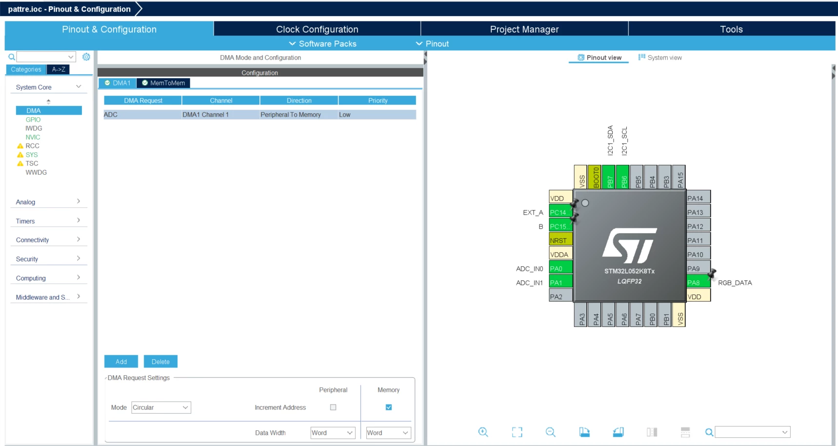
Screenshot 2024-07-24 102732.png

This topic has been closed for replies.
KnarfB
KnarfBBest answer
Super User
July 24, 2024
hadc.Init.DMAContinuousRequests = DISABLE;

is wrong, must be enabled.

hth

KnarfB

5 replies

KnarfB
KnarfBBest answer
Super User
July 24, 2024
hadc.Init.DMAContinuousRequests = DISABLE;

is wrong, must be enabled.

hth

KnarfB

vijay_66Author
Associate
July 31, 2024

As you said to ENABLE hadc.Init.DMAContinuousRequests. I done it, but it's not working. After enabling it, lcd not printing anything

/* USER CODE BEGIN Header */
/**
 ******************************************************************************
 * @file : main.c
 * @brief : Main program body
 ******************************************************************************
 * @attention
 *
 * Copyright (c) 2024 STMicroelectronics.
 * All rights reserved.
 *
 * This software is licensed under terms that can be found in the LICENSE file
 * in the root directory of this software component.
 * If no LICENSE file comes with this software, it is provided AS-IS.
 *
 ******************************************************************************
 */
/* USER CODE END Header */
/* Includes ------------------------------------------------------------------*/
#include "main.h"

/* Private includes ----------------------------------------------------------*/
/* USER CODE BEGIN Includes */
#include "lcd.h"
#include "stdio.h"
#include "string.h"

/* USER CODE END Includes */

/* Private typedef -----------------------------------------------------------*/
/* USER CODE BEGIN PTD */
typedef struct {
	uint8_t B;
	uint8_t R;
	uint8_t G;
} WS2812B_RGB_t;

typedef union {
	uint32_t U;
	WS2812B_RGB_t color;
} WS2812B_color_t;
/* USER CODE END PTD */

/* Private define ------------------------------------------------------------*/
/* USER CODE BEGIN PD */

/* USER CODE END PD */

/* Private macro -------------------------------------------------------------*/
/* USER CODE BEGIN PM */

#define ENCODER_PIN_A GPIO_PIN_14
#define ENCODER_PIN_B GPIO_PIN_15
#define ENCODER_PORT GPIOC

/* USER CODE END PM */

/* Private variables ---------------------------------------------------------*/
ADC_HandleTypeDef hadc;
DMA_HandleTypeDef hdma_adc;

I2C_HandleTypeDef hi2c1;

/* USER CODE BEGIN PV */
int value1;
int value2;

uint32_t value[2];

float result1 = 0;
float result2 = 0;

char buffer1[100];
char buffer2[100];

volatile uint32_t encoder_count = 0;
/* USER CODE END PV */

/* Private function prototypes -----------------------------------------------*/
void SystemClock_Config(void);
static void MX_GPIO_Init(void);
static void MX_DMA_Init(void);
static void MX_I2C1_Init(void);
static void MX_ADC_Init(void);
/* USER CODE BEGIN PFP */

/* USER CODE END PFP */

/* Private user code ---------------------------------------------------------*/
/* USER CODE BEGIN 0 */

void __attribute__ ((optimize("-Ofast"))) led(uint32_t grb) {
	uint_fast32_t mask = 0x00800000;

	for (uint_fast8_t i = 0; i < 24; i++) {
		if (grb & mask) {
			RGB_DATA_GPIO_Port->BSRR = RGB_DATA_Pin;
			__NOP();
			__NOP();
			__NOP();
			__NOP();
			__NOP();
			__NOP();
			__NOP();
			__NOP();
			__NOP();
			__NOP();
			__NOP();
			__NOP();
			RGB_DATA_GPIO_Port->BRR = RGB_DATA_Pin;
			__NOP();
			__NOP();
			__NOP();
			__NOP();__NOP();
		} else {
			RGB_DATA_GPIO_Port->BSRR = RGB_DATA_Pin;
			__NOP();
			__NOP();
			__NOP();
			__NOP();
			__NOP();
			RGB_DATA_GPIO_Port->BRR = RGB_DATA_Pin;
			__NOP();
			__NOP();
			__NOP();
			__NOP();
			__NOP();
			__NOP();
			__NOP();
			__NOP();
			__NOP();__NOP();
		}
		mask >>= 1;
	}
}

void WS28122B_Write_LED(uint32_t *data) {
	for (uint8_t i = 0; i < 12; i++) {
		led(data[i]);
	}
}

/* USER CODE END 0 */

/**
 * @brief The application entry point.
 * @retval int
 */
int main(void) {

	/* USER CODE BEGIN 1 */

	/* USER CODE END 1 */

	/* MCU Configuration--------------------------------------------------------*/

	/* Reset of all peripherals, Initializes the Flash interface and the Systick. */
	HAL_Init();

	/* USER CODE BEGIN Init */

	/* USER CODE END Init */

	/* Configure the system clock */
	SystemClock_Config();

	/* USER CODE BEGIN SysInit */

	/* USER CODE END SysInit */

	/* Initialize all configured peripherals */
	MX_GPIO_Init();
	MX_DMA_Init();
	MX_I2C1_Init();
	MX_ADC_Init();
	/* USER CODE BEGIN 2 */
	HAL_ADC_Start_DMA(&hadc, value, 2);
	
	lcd_init(&hi2c1);
	lcd_set_cursor_style(&hi2c1, 0X0C);

	/* USER CODE END 2 */

	/* Infinite loop */
	/* USER CODE BEGIN WHILE */

// WS2812B_color_t led1={0};
// led1.U=0xff00;
// led1.color.G;
// uint32_t led_data[12]={0x550000,0x5500, 0x55, 0x550000,0x5500, 0x55,0x550000,0x5500, 0x55, 0x550000,0x5500, 0x55};
// WS28122B_Write_LED(led_data);

	while (1) {


		result1 = (3.3 * value[0]) / 4095;
		sprintf(buffer1, "ADC1: %04d, %.2f", (int) value[0], result1);
		lcd_goto_rc(&hi2c1, 0, 0);
		lcd_putstr(&hi2c1, buffer1);

		result2 = (3.3 * value[1]) / 4095;
		sprintf(buffer2, "ADC2: %04d, %.2f", (int) value[1], result2);
		lcd_goto_rc(&hi2c1, 1, 0);
		lcd_putstr(&hi2c1, buffer2);

		/* USER CODE END WHILE */

		/* USER CODE BEGIN 3 */
	}
	/* USER CODE END 3 */
}

/**
 * @brief System Clock Configuration
 * @retval None
 */
void SystemClock_Config(void) {
	RCC_OscInitTypeDef RCC_OscInitStruct = { 0 };
	RCC_ClkInitTypeDef RCC_ClkInitStruct = { 0 };
	RCC_PeriphCLKInitTypeDef PeriphClkInit = { 0 };

	/** Configure the main internal regulator output voltage
	 */
	__HAL_PWR_VOLTAGESCALING_CONFIG(PWR_REGULATOR_VOLTAGE_SCALE1);

	/** Initializes the RCC Oscillators according to the specified parameters
	 * in the RCC_OscInitTypeDef structure.
	 */
	RCC_OscInitStruct.OscillatorType = RCC_OSCILLATORTYPE_HSI;
	RCC_OscInitStruct.HSIState = RCC_HSI_ON;
	RCC_OscInitStruct.HSICalibrationValue = RCC_HSICALIBRATION_DEFAULT;
	RCC_OscInitStruct.PLL.PLLState = RCC_PLL_ON;
	RCC_OscInitStruct.PLL.PLLSource = RCC_PLLSOURCE_HSI;
	RCC_OscInitStruct.PLL.PLLMUL = RCC_PLLMUL_4;
	RCC_OscInitStruct.PLL.PLLDIV = RCC_PLLDIV_2;
	if (HAL_RCC_OscConfig(&RCC_OscInitStruct) != HAL_OK) {
		Error_Handler();
	}

	/** Initializes the CPU, AHB and APB buses clocks
	 */
	RCC_ClkInitStruct.ClockType = RCC_CLOCKTYPE_HCLK | RCC_CLOCKTYPE_SYSCLK
			| RCC_CLOCKTYPE_PCLK1 | RCC_CLOCKTYPE_PCLK2;
	RCC_ClkInitStruct.SYSCLKSource = RCC_SYSCLKSOURCE_PLLCLK;
	RCC_ClkInitStruct.AHBCLKDivider = RCC_SYSCLK_DIV1;
	RCC_ClkInitStruct.APB1CLKDivider = RCC_HCLK_DIV1;
	RCC_ClkInitStruct.APB2CLKDivider = RCC_HCLK_DIV1;

	if (HAL_RCC_ClockConfig(&RCC_ClkInitStruct, FLASH_LATENCY_1) != HAL_OK) {
		Error_Handler();
	}
	PeriphClkInit.PeriphClockSelection = RCC_PERIPHCLK_I2C1;
	PeriphClkInit.I2c1ClockSelection = RCC_I2C1CLKSOURCE_PCLK1;
	if (HAL_RCCEx_PeriphCLKConfig(&PeriphClkInit) != HAL_OK) {
		Error_Handler();
	}
}

/**
 * @brief ADC Initialization Function
 * @PAram None
 * @retval None
 */
static void MX_ADC_Init(void) {

	/* USER CODE BEGIN ADC_Init 0 */

	/* USER CODE END ADC_Init 0 */

	ADC_ChannelConfTypeDef sConfig = { 0 };

	/* USER CODE BEGIN ADC_Init 1 */

	/* USER CODE END ADC_Init 1 */

	/** Configure the global features of the ADC (Clock, Resolution, Data Alignment and number of conversion)
	 */
	hadc.Instance = ADC1;
	hadc.Init.OversamplingMode = DISABLE;
	hadc.Init.ClockPrescaler = ADC_CLOCK_SYNC_PCLK_DIV2;
	hadc.Init.Resolution = ADC_RESOLUTION_12B;
	hadc.Init.SamplingTime = ADC_SAMPLETIME_1CYCLE_5;
	hadc.Init.ScanConvMode = ADC_SCAN_DIRECTION_FORWARD;
	hadc.Init.DataAlign = ADC_DATAALIGN_RIGHT;
	hadc.Init.ContinuousConvMode = ENABLE;
	hadc.Init.DiscontinuousConvMode = DISABLE;
	hadc.Init.ExternalTrigConvEdge = ADC_EXTERNALTRIGCONVEDGE_NONE;
	hadc.Init.ExternalTrigConv = ADC_SOFTWARE_START;
	hadc.Init.DMAContinuousRequests = ENABLE;
	hadc.Init.EOCSelection = ADC_EOC_SINGLE_CONV;
	hadc.Init.Overrun = ADC_OVR_DATA_PRESERVED;
	hadc.Init.LowPowerAutoWait = DISABLE;
	hadc.Init.LowPowerFrequencyMode = DISABLE;
	hadc.Init.LowPowerAutoPowerOff = DISABLE;
	if (HAL_ADC_Init(&hadc) != HAL_OK) {
		Error_Handler();
	}

	/** Configure for the selected ADC regular channel to be converted.
	 */
	sConfig.Channel = ADC_CHANNEL_0;
	sConfig.Rank = ADC_RANK_CHANNEL_NUMBER;
	if (HAL_ADC_ConfigChannel(&hadc, &sConfig) != HAL_OK) {
		Error_Handler();
	}

	/** Configure for the selected ADC regular channel to be converted.
	 */
	sConfig.Channel = ADC_CHANNEL_1;
	if (HAL_ADC_ConfigChannel(&hadc, &sConfig) != HAL_OK) {
		Error_Handler();
	}
	/* USER CODE BEGIN ADC_Init 2 */

	/* USER CODE END ADC_Init 2 */

}

/**
 * @brief I2C1 Initialization Function
 * @PAram None
 * @retval None
 */
static void MX_I2C1_Init(void) {

	/* USER CODE BEGIN I2C1_Init 0 */

	/* USER CODE END I2C1_Init 0 */

	/* USER CODE BEGIN I2C1_Init 1 */

	/* USER CODE END I2C1_Init 1 */
	hi2c1.Instance = I2C1;
	hi2c1.Init.Timing = 0x00707CBB;
	hi2c1.Init.OwnAddress1 = 0;
	hi2c1.Init.AddressingMode = I2C_ADDRESSINGMODE_7BIT;
	hi2c1.Init.DualAddressMode = I2C_DUALADDRESS_DISABLE;
	hi2c1.Init.OwnAddress2 = 0;
	hi2c1.Init.OwnAddress2Masks = I2C_OA2_NOMASK;
	hi2c1.Init.GeneralCallMode = I2C_GENERALCALL_DISABLE;
	hi2c1.Init.NoStretchMode = I2C_NOSTRETCH_DISABLE;
	if (HAL_I2C_Init(&hi2c1) != HAL_OK) {
		Error_Handler();
	}

	/** Configure Analogue filter
	 */
	if (HAL_I2CEx_ConfigAnalogFilter(&hi2c1, I2C_ANALOGFILTER_ENABLE)
			!= HAL_OK) {
		Error_Handler();
	}

	/** Configure Digital filter
	 */
	if (HAL_I2CEx_ConfigDigitalFilter(&hi2c1, 0) != HAL_OK) {
		Error_Handler();
	}
	/* USER CODE BEGIN I2C1_Init 2 */

	/* USER CODE END I2C1_Init 2 */

}

/**
 * Enable DMA controller clock
 */
static void MX_DMA_Init(void) {

	/* DMA controller clock enable */
	__HAL_RCC_DMA1_CLK_ENABLE();

	/* DMA interrupt init */
	/* DMA1_Channel1_IRQn interrupt configuration */
	HAL_NVIC_SetPriority(DMA1_Channel1_IRQn, 0, 0);
	HAL_NVIC_EnableIRQ(DMA1_Channel1_IRQn);

}

/**
 * @brief GPIO Initialization Function
 * @PAram None
 * @retval None
 */
static void MX_GPIO_Init(void) {
	GPIO_InitTypeDef GPIO_InitStruct = { 0 };
	/* USER CODE BEGIN MX_GPIO_Init_1 */
	/* USER CODE END MX_GPIO_Init_1 */

	/* GPIO Ports Clock Enable */
	__HAL_RCC_GPIOC_CLK_ENABLE();
	__HAL_RCC_GPIOA_CLK_ENABLE();
	__HAL_RCC_GPIOB_CLK_ENABLE();

	/*Configure GPIO pin Output Level */
	HAL_GPIO_WritePin(RGB_DATA_GPIO_Port, RGB_DATA_Pin, GPIO_PIN_RESET);

	/*Configure GPIO pin : EXT_A_Pin */
	GPIO_InitStruct.Pin = EXT_A_Pin;
	GPIO_InitStruct.Mode = GPIO_MODE_IT_RISING_FALLING;
	GPIO_InitStruct.Pull = GPIO_PULLUP;
	HAL_GPIO_Init(ENCODER_PORT, &GPIO_InitStruct);

	/*Configure GPIO pin : B_Pin */
	GPIO_InitStruct.Pin = B_Pin;
	GPIO_InitStruct.Mode = GPIO_MODE_INPUT;
	GPIO_InitStruct.Pull = GPIO_PULLUP;
	HAL_GPIO_Init(ENCODER_PORT, &GPIO_InitStruct);

	/*Configure GPIO pin : RGB_DATA_Pin */
	GPIO_InitStruct.Pin = RGB_DATA_Pin;
	GPIO_InitStruct.Mode = GPIO_MODE_OUTPUT_PP;
	GPIO_InitStruct.Pull = GPIO_NOPULL;
	GPIO_InitStruct.Speed = GPIO_SPEED_FREQ_LOW;
	HAL_GPIO_Init(RGB_DATA_GPIO_Port, &GPIO_InitStruct);

	/* EXTI interrupt init*/
	HAL_NVIC_SetPriority(EXTI4_15_IRQn, 0, 0);
	HAL_NVIC_EnableIRQ(EXTI4_15_IRQn);

	/* USER CODE BEGIN MX_GPIO_Init_2 */
	/* USER CODE END MX_GPIO_Init_2 */
}

/* USER CODE BEGIN 4 */
//static void MX_NVIC_Init(void){
//	HAL_NVIC_SetPriority(EXTI4_15_IRQn, 0, 0);
//	HAL_NVIC_EnableIRQ(EXTI4_15_IRQn);
//}
/* USER CODE END 4 */

/**
 * @brief This function is executed in case of error occurrence.
 * @retval None
 */
void Error_Handler(void) {
	/* USER CODE BEGIN Error_Handler_Debug */
	/* User can add his own implementation to report the HAL error return state */
	__disable_irq();
	while (1) {
	}
	/* USER CODE END Error_Handler_Debug */
}

#ifdef USE_FULL_ASSERT
/**
 * @brief Reports the name of the source file and the source line number
 * where the assert_param error has occurred.
 * @PAram file: pointer to the source file name
 * @PAram line: assert_param error line source number
 * @retval None
 */
void assert_failed(uint8_t *file, uint32_t line)
{
 /* USER CODE BEGIN 6 */
 /* User can add his own implementation to report the file name and line number,
 ex: printf("Wrong parameters value: file %s on line %d\r\n", file, line) */
 /* USER CODE END 6 */
}
#endif /* USE_FULL_ASSERT */

LCE
Principal III
July 24, 2024

First of all, please use the "</>" button to post your source code.

Then, what KnarfB said, and have you set the DMA to CIRCULAR? Or doesn't this STM have this DMA feature?

vijay_66Author
Associate
July 31, 2024
