


Question
Timer 8 issue in Cube IDE V1.5.0
When generating Code for STM32H753IIKx I recently stumbled across unexpected behaviour in Cube IDE V1.5.0. I'm using the processor Pins PH13-PH15 in order to output a PWM Signal from the N-Outputs of Timer 8 (CH1N1-3). However no correlating signals were observed.
My timer initialization:
static void MX_TIM8_Init(void)
{

 /* USER CODE BEGIN TIM8_Init 0 */

 /* USER CODE END TIM8_Init 0 */

 TIM_MasterConfigTypeDef sMasterConfig = {0};
 TIM_OC_InitTypeDef sConfigOC = {0};
 TIM_BreakDeadTimeConfigTypeDef sBreakDeadTimeConfig = {0};

 /* USER CODE BEGIN TIM8_Init 1 */

 /* USER CODE END TIM8_Init 1 */
 htim8.Instance = TIM8;
 htim8.Init.Prescaler = 2000-1;
 htim8.Init.CounterMode = TIM_COUNTERMODE_UP;
 htim8.Init.Period = 255-1;
 htim8.Init.ClockDivision = TIM_CLOCKDIVISION_DIV1;
 htim8.Init.RepetitionCounter = 0;
 htim8.Init.AutoReloadPreload = TIM_AUTORELOAD_PRELOAD_ENABLE;
 if (HAL_TIM_PWM_Init(&htim8) != HAL_OK)
 {
 Error_Handler();
 }
 sMasterConfig.MasterOutputTrigger = TIM_TRGO_RESET;
 sMasterConfig.MasterOutputTrigger2 = TIM_TRGO2_RESET;
 sMasterConfig.MasterSlaveMode = TIM_MASTERSLAVEMODE_DISABLE;
 if (HAL_TIMEx_MasterConfigSynchronization(&htim8, &sMasterConfig) != HAL_OK)
 {
 Error_Handler();
 }
 sConfigOC.OCMode = TIM_OCMODE_PWM1;
 sConfigOC.Pulse = 255-1;
 sConfigOC.OCPolarity = TIM_OCPOLARITY_HIGH;
 sConfigOC.OCNPolarity = TIM_OCNPOLARITY_HIGH;
 sConfigOC.OCFastMode = TIM_OCFAST_DISABLE;
 sConfigOC.OCIdleState = TIM_OCIDLESTATE_RESET;
 sConfigOC.OCNIdleState = TIM_OCNIDLESTATE_RESET;
 if (HAL_TIM_PWM_ConfigChannel(&htim8, &sConfigOC, TIM_CHANNEL_1) != HAL_OK)
 {
 Error_Handler();
 }
 if (HAL_TIM_PWM_ConfigChannel(&htim8, &sConfigOC, TIM_CHANNEL_2) != HAL_OK)
 {
 Error_Handler();
 }
 if (HAL_TIM_PWM_ConfigChannel(&htim8, &sConfigOC, TIM_CHANNEL_3) != HAL_OK)
 {
 Error_Handler();
 }
 sBreakDeadTimeConfig.OffStateRunMode = TIM_OSSR_DISABLE;
 sBreakDeadTimeConfig.OffStateIDLEMode = TIM_OSSI_DISABLE;
 sBreakDeadTimeConfig.LockLevel = TIM_LOCKLEVEL_OFF;
 sBreakDeadTimeConfig.DeadTime = 0;
 sBreakDeadTimeConfig.BreakState = TIM_BREAK_DISABLE;
 sBreakDeadTimeConfig.BreakPolarity = TIM_BREAKPOLARITY_HIGH;
 sBreakDeadTimeConfig.BreakFilter = 0;
 sBreakDeadTimeConfig.Break2State = TIM_BREAK2_DISABLE;
 sBreakDeadTimeConfig.Break2Polarity = TIM_BREAK2POLARITY_HIGH;
 sBreakDeadTimeConfig.Break2Filter = 0;
 sBreakDeadTimeConfig.AutomaticOutput = TIM_AUTOMATICOUTPUT_DISABLE;
 if (HAL_TIMEx_ConfigBreakDeadTime(&htim8, &sBreakDeadTimeConfig) != HAL_OK)
 {
 Error_Handler();
 }
 /* USER CODE BEGIN TIM8_Init 2 */

 HAL_TIM_PWM_ConfigChannel(&htim8, &sConfigOC, TIM_CHANNEL_1);
 HAL_TIM_PWM_ConfigChannel(&htim8, &sConfigOC, TIM_CHANNEL_2);
 HAL_TIM_PWM_ConfigChannel(&htim8, &sConfigOC, TIM_CHANNEL_3);

 HAL_TIM_PWM_Start_DMA(&htim8, TIM_CHANNEL_1, (uint32_t*)&RGB_array[0], 1);
 HAL_TIM_PWM_Start_DMA(&htim8, TIM_CHANNEL_2, (uint32_t*)&RGB_array[1], 1);
 HAL_TIM_PWM_Start_DMA(&htim8, TIM_CHANNEL_3, (uint32_t*)&RGB_array[2], 1);
 /* USER CODE END TIM8_Init 2 */
 HAL_TIM_MspPostInit(&htim8);

}
Cube IDE Setting:
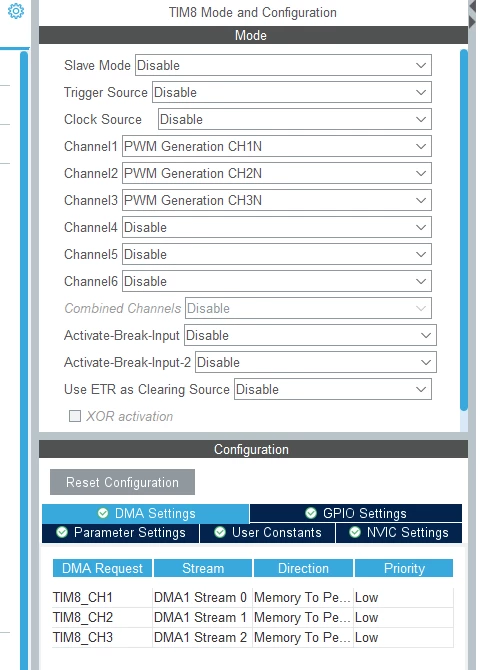 Further investigation showed, that registers for controlling the driver stage were not set accordingly in the peripheral. Only the complementary outputs of the PWM stage were enabled (CH1-3).
Writing to the registers manually later on (outside of the auto-generated codeblock) solved the issue:
htim8.Instance->CCER = (1UL << 2) | (1UL << 6) | (1UL << 10);Is this a bug or are there underlying mechanics which I'm not realizing?