STM32H7A3ZIT6Q – Firmware Programming Successful but GPIO Outputs Not Working on Custom PCB
Hello ST Community,
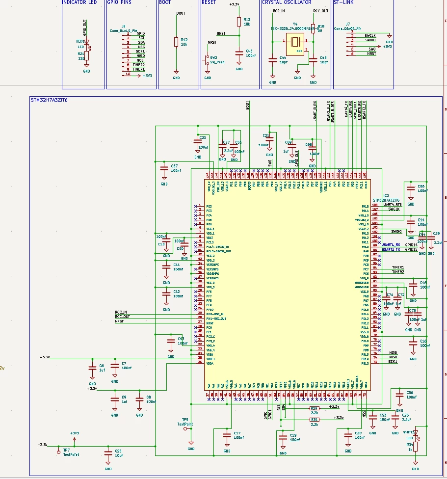
I am currently developing a custom PCB based on the STM32H7A3ZIT6Q (LQFP144) microcontroller. I am facing an issue where the MCU can be successfully programmed using ST-LINK, but its GPIO pins do not appear to operate as expected.
I would appreciate some guidance in identifying whether this could be related to the power supply configuration, internal regulator settings, clock configuration, or GPIO initialization.
1. Hardware Configuration
-
MCU: STM32H7A3ZIT6Q
-
Package: LQFP144
-
PCB: Custom-designed 2-layer PCB
-
Programming interface: ST-LINK/V2
-
Target voltage: 3.3V
-
Power configuration: Internal LDO mode
-
External crystal: 24 MHz
The MCU is powered from an external 3.3V regulated supply.
2. Programming Status
I can successfully connect to the MCU using STM32CubeIDE and STM32CubeProgrammer.
The ST-LINK log reports:
-
ST-LINK Firmware: V2J49S7
-
Target Voltage: 3.30V
-
Device ID: 0x480
-
Device Name: STM32H7A/B
-
Flash Size: 2 MB
-
SWD Frequency: 4000 KHz
The firmware download and verification complete successfully, with the message:
Download verified successfully
Therefore, the ST-LINK can communicate with the target MCU and program its internal flash.
3. Power Supply Configuration
In my SystemClock_Config() function, I am currently using:
HAL_PWREx_ConfigSupply(PWR_LDO_SUPPLY);The voltage scaling is configured as:
__HAL_PWR_VOLTAGESCALING_CONFIG(PWR_REGULATOR_VOLTAGE_SCALE3);I am currently using the internal HSI oscillator as the system clock source, with PLL disabled.
RCC_OscInitStruct.OscillatorType = RCC_OSCILLATORTYPE_HSI;
RCC_OscInitStruct.HSIState = RCC_HSI_DIV1;
RCC_OscInitStruct.PLL.PLLState = RCC_PLL_NONE;

RCC_ClkInitStruct.SYSCLKSource = RCC_SYSCLKSOURCE_HSI;
4. GPIO Configuration and Testing
I initially tried testing GPIO PC12, PB1, and PF15.
For PF15, I configured the pin as:
-
Mode: GPIO Output Push-Pull
-
Pull-up/Pull-down: No Pull
-
Output Speed: Low
-
GPIOF clock enabled
My GPIO initialization code is:
__HAL_RCC_GPIOF_CLK_ENABLE();

HAL_GPIO_WritePin(GPIOF, GPIO_PIN_15, GPIO_PIN_RESET);

GPIO_InitStruct.Pin = GPIO_PIN_15;
GPIO_InitStruct.Mode = GPIO_MODE_OUTPUT_PP;
GPIO_InitStruct.Pull = GPIO_NOPULL;
GPIO_InitStruct.Speed = GPIO_SPEED_FREQ_LOW;

HAL_GPIO_Init(GPIOF, &GPIO_InitStruct);
For testing, I am using the following code inside the main while loop:
while (1)
{
    HAL_GPIO_WritePin(GPIOF, GPIO_PIN_15, GPIO_PIN_SET);
    HAL_Delay(2000);

    HAL_GPIO_WritePin(GPIOF, GPIO_PIN_15, GPIO_PIN_RESET);
    HAL_Delay(2000);
}
5. Observed Problem
Despite successful firmware programming and verification:
-
The LED connected to PF15 remains continuously ON.
-
The PF15 output appears to remain at approximately 3.3V.
-
I do not observe the expected HIGH-to-LOW transitions.
-
Similar GPIO testing on other pins has also not produced the expected results.
I have also checked that the GPIO port clock is enabled and that the GPIO is configured as an output.
6. Questions
I would appreciate your help with the following:
-
Could this issue be related to the internal LDO or SMPS power configuration of the STM32H7A3ZIT6Q?
-
Are there any additional power supply connections or configurations required for the LDO mode?
-
Is there any specific initialization sequence required before enabling GPIO functionality?
-
Could the VCAP, VDDLDO, VDDSMPS, or other power-related pins cause this type of GPIO malfunction if incorrectly connected?
-
Is there a recommended procedure to verify whether the Cortex-M7 core is executing the application code correctly?
-
Could any GPIO-related configuration, alternate-function assignment, or hardware restriction prevent PF15 from operating as a standard GPIO?
My main objective is to verify the basic GPIO functionality of my custom PCB before proceeding with other peripherals such as UART, SPI, I2C, and RS485.
I can also share my complete power supply schematic, PCB layout, and STM32CubeIDE configuration for further investigation.
Thank you for your time and support.
Best regards
schematics: