


FranzCreva
Associate II
November 21, 2022
Solved

STM32G0 bought with level 2 protection

Hi all, I'm new to this STM32 community.

I have a small problem: I bought some STM32G0P0.. for my project, also making the PCB and the rest. But after soldering the various components, I try to program one and see that the level 2 protection is active, I try to program another and there is the same thing.

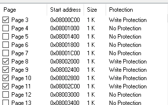
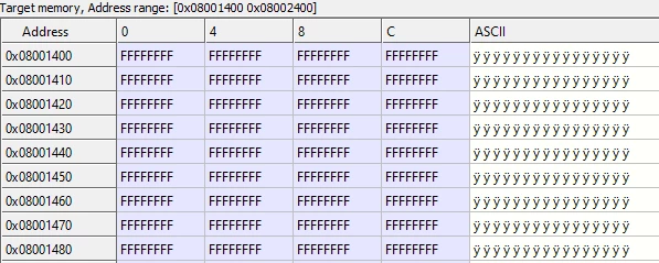
What I see from the STM32 St-LINK program is that only some memory pages have protection, while others don't, but then going to view the memory areas I see that they have all been set to FFFFFFFF.

Below I can see that the memory on the address 0x08001400 is free, but..
0693W00000WIxGqQAL.png 

..here I see that is protected! How can I program it?
0693W00000WIxHFQA1.png 

My question now is: what the hell do I do? Do I ask for a return? Is this a normal thing of STM32G0...? Trying to write a bootloader that makes me jump from one address to another when the memory to read is full?

Thank you for your availability and attention

This topic has been closed for replies.
FranzCreva
FranzCrevaBest answer
Associate II
January 6, 2023

Hi @mattias norlander​ .

You're right, I had already intended to select the best answer, but I think it's better to make a small summary with the answer as well?

We can say that the title "STM32G0 bought with level 2 protection" has nothing to do with the final solution, but I can explain that I thought the MCU has level 2 protection because the STM32 ST-LINK Utility" program is outdated, so using STM32CubeIDEProgrammer was able to connect to the MCU correctly.

After that I tried to debug with STM32CubeIDE, but I couldn't. This was due to the fact that the nBOOT0 entry (in the "user configuration option byte" section) had not been flagged (for your MCU look at the Boot Mode configuration even though almost all MCUs have the same configurations).

The nBOOT0 flag fixed the problem and it was thanks to the advice of @Piranha​ .

I also have to thank @Community member​ , @AScha.3​ and the others (@mattias norlander​ you are included).

63 replies

AScha.3
Super User
November 29, 2022

good ! so (on this board) all ok, cpu working and connection ok. -> can work with ST...programmer.

+

Ide: something you still wrong/bad adjusted.

try: in debug settings: SWD , 4MHz (or lower) ; resetmode: software system reset , + enablew low power ,+ stop watchdog.

If you feel a post has answered your question, please click on " Best Answer ".
FranzCreva
Associate II
December 6, 2022

@AScha.3​  and @Community member​ nothing changes!! I've been here for now 2-3 weeks and nothing is working.

The scheduling and degubbing configurations are:

Run configuration

0693W00000WKNyRQAX.png 

Debug configuration:

0693W00000WKNz0QAH.png0693W00000WKNzAQAX.png 

If someone could figure out what's wrong with the messages I get on the console it would be a huge favor:

Run messages console

Open On-Chip Debugger 0.11.0+dev-00449-g53fa0f7 (2022-06-09-09:42) [https://github.com/STMicroelectronics/OpenOCD]
Licensed under GNU GPL v2
For bug reports, read
	http://openocd.org/doc/doxygen/bugs.html
Info : Listening on port 6666 for tcl connections
Info : Listening on port 4444 for telnet connections
Info : STLINK V2J40S7 (API v2) VID:PID 0483:3748
Info : Target voltage: 3.244561
Info : clock speed 950 kHz
Info : stlink_dap_op_connect(connect)
Info : SWD DPIDR 0x0bc11477
Info : STM32G050F6Px.cpu: Cortex-M0+ r0p1 processor detected
Info : STM32G050F6Px.cpu: target has 4 breakpoints, 2 watchpoints
Info : starting gdb server for STM32G050F6Px.cpu on 3333
Info : Listening on port 3333 for gdb connections
Info : accepting 'gdb' connection on tcp/3333
Info : device idcode = 0x10006456 (STM32G05/G06xx - Rev A : 0x1000)
Info : RDP level 0 (0xAA)
Info : flash size = 32kbytes
Info : flash mode : single-bank
undefined debug reason 8 - target needs reset
Info : accepting 'gdb' connection on tcp/3333
undefined debug reason 8 - target needs reset
target halted due to debug-request, current mode: Thread 
xPSR: 0xf1000000 pc: 0x1fff1654 msp: 0x20000e48
target halted due to debug-request, current mode: Thread 
xPSR: 0xf1000000 pc: 0x1fff1654 msp: 0x20000e48
Info : STM32G050F6Px.cpu: external reset detected
Info : dropped 'gdb' connection
target halted due to debug-request, current mode: Thread 
xPSR: 0x41000000 pc: 0x1fff1274 msp: 0x20000e28
shutdown command invoked
Info : dropped 'gdb' connection

and this message

0693W00000WKNzPQAX.png 

The DEBUG console

Open On-Chip Debugger 0.11.0+dev-00449-g53fa0f7 (2022-06-09-09:42) [https://github.com/STMicroelectronics/OpenOCD]
Licensed under GNU GPL v2
For bug reports, read
	http://openocd.org/doc/doxygen/bugs.html
Info : Listening on port 6666 for tcl connections
Info : Listening on port 4444 for telnet connections
Info : STLINK V2J40S7 (API v2) VID:PID 0483:3748
Info : Target voltage: 3.242988
Info : clock speed 950 kHz
Info : stlink_dap_op_connect(connect)
Info : SWD DPIDR 0x0bc11477
Info : STM32G050F6Px.cpu: Cortex-M0+ r0p1 processor detected
Info : STM32G050F6Px.cpu: target has 4 breakpoints, 2 watchpoints
Info : starting gdb server for STM32G050F6Px.cpu on 3333
Info : Listening on port 3333 for gdb connections
Info : accepting 'gdb' connection on tcp/3333
Info : device idcode = 0x10006456 (STM32G05/G06xx - Rev A : 0x1000)
Info : RDP level 0 (0xAA)
Info : flash size = 32kbytes
Info : flash mode : single-bank
undefined debug reason 8 - target needs reset
Info : accepting 'gdb' connection on tcp/3333
undefined debug reason 8 - target needs reset
target halted due to debug-request, current mode: Thread 
xPSR: 0xf1000000 pc: 0x1fff1654 msp: 0x20000e48
target halted due to debug-request, current mode: Thread 
xPSR: 0xf1000000 pc: 0x1fff1654 msp: 0x20000e48

and this message:

0693W00000WKO03QAH.png 

Thanks for your availability.

Tesla DeLorean
Guru
December 7, 2022

I don't work for ST, you'll need to raise those responsible for CubeIDE and the integration of assorted components.

The 0x1FFFxxxx addresses are indicative of being in the boot-loader.

Perhaps support for STM32G0 is not where it needs to be, I'll flag this upward.

Tips, Buy me a coffee, or three.. PayPal Venmo (See Profile) Up vote any posts that you find helpful, it shows what's working..
AScha.3
Super User
December 7, 2022

Ooo,

0693W00000WKO9jQAH.pngset:

  • automated
  • 4 MHz
  • software system reset
  • keep pin boot0 lo , at gnd.

If you feel a post has answered your question, please click on " Best Answer ".
FranzCreva
Associate II
December 9, 2022

No no, this is not my configuration, I don't know how I managed to take this screenshot.

However my configuration is the same except for the Speed, which I set at 950khz, since with STM32Programmer I can connect to the device with that frequency and not with 4MHz.

If I try to set the speed to 4MHz I get this error:

0693W00000WKb7bQAD.png 

and this message:

Open On-Chip Debugger 0.11.0+dev-00449-g53fa0f7 (2022-06-09-09:42) [https://github.com/STMicroelectronics/OpenOCD]
Licensed under GNU GPL v2
For bug reports, read
	http://openocd.org/doc/doxygen/bugs.html
Info : Listening on port 6666 for tcl connections
Info : Listening on port 4444 for telnet connections
Info : STLINK V2J40S7 (API v2) VID:PID 0483:3748
Info : Target voltage: 3.229377
Info : clock speed 4000 kHz
Info : stlink_dap_op_connect(connect)

Instead when I try to program it I get the same error as before, but with this message:

Open On-Chip Debugger 0.11.0+dev-00449-g53fa0f7 (2022-06-09-09:42) [https://github.com/STMicroelectronics/OpenOCD]
Licensed under GNU GPL v2
For bug reports, read
	http://openocd.org/doc/doxygen/bugs.html
Info : Listening on port 6666 for tcl connections
Info : Listening on port 4444 for telnet connections
Info : STLINK V2J40S7 (API v2) VID:PID 0483:3748
Info : Target voltage: 3.254557
Error: init mode failed (unable to connect to the target)

mattias norlander
ST Employee
December 7, 2022

Hi @FranzCreva,

It seems as if you are using CubeIDE version 1.10.1.

In CubeIDE 1.11.0 released last week CubeIDE is slightly better able to detect when CubeProg CLI fails to flash and can abort the debug session a little bit earlier. That said, error handling is still an issue where one root-cause is missing granularity on return codes from CubeProg CLI. And it is unlikely to solve your issues, so no need to update for you.

Question1: Is the application you are developing putting MCU in low-power modes?

If so, you must use:

  • Reset strategy = Connect under reset
  • Enable debug in low-power modes

Not using these options should give you the error shown in the first dialogs: "No device found on target".

Reading this thread it seems as if you are able to use CubeProg stand-alone version in GUI mode to program the device.

Meanwhile inside CubeIDE when IDE is calling CubeProg to do the programming you end up with :

Error: No STM32 target found!
Encountered Error when opening C:\ST\STM32CubeIDE_1.10.1\STM32CubeIDE\plugins\com.st.stm32cube.ide.mcu.externaltools.cubeprogrammer.win32_2.0.301.202207041506\tools\bin\STM32_Programmer_CLI.exe
Error in STM32CubeProgrammer
Shutting down...
Exit.

This makes me curious... I don't have access to a STM32G0... board even less to your custom PCB.

Here is my train of thoughts:

  • CubeProg GUI version flashes the board OK
  • Can CubeProg CLI version flash the board OK?
    • CubeIDE uses CLI version, not GUI version. They rely on same flash loader, but let's make "Test1"

Test1: Try to flash your application relying on CubeProg CLI by using this command:

C:\ST\STM32CubeIDE_1.10.1\STM32CubeIDE\plugins\com.st.stm32cube.ide.mcu.externaltools.cubeprogrammer.win32_2.0.301.202207041506\tools\bin\STM32_Programmer_CLI.exe -c port=SWD -d C:\Users\norlandm\STM32CubeIDE\workspace_IPCEI\STM32F4_RTOS\Debug\STM32F4_RTOS.elf

Obviously you need to modify the two paths in the above example. Does Test1 work well or not?

If not, then we know that the root-cause is isolated to CubeProg CLI ( or potentially the flash loader).

I think this test will be successful. But we have to execute it anyway to narrow down the scope!

Next thought is related to this screenshot of yours:

Here I am thinking that there could be an issue inside the flash loader. If the flash loader does not de-initialize the resources it uses (specifically interrupts) it will leave the MCU in a dirty state.

The effect can be that CubeProg stand-alone can flash the MCU correctly. What you may or may not notice is that the CPU is crashed afterwards depending on how CubeProg applies resets afterwards...

This leads us to Test2:

  1. Use CubeProg stand-alone GUI version to flash your application
  2. Disconnect CubeProg. De-tach and re-attach the board to your PC
  3. In CubeIDE setup a debug configuration which does NOT load the elf-file to target. Use default settings in the debug configuration (use ST-LINK GDB server) and then make these specific settings:
    1. Reset strategy : Connect under reset
    2. Enable low power debug modes (just to be safe)
    3. In the Startup tab > Load Image and Symbols > Debug/myproject.elf > Edit
      1. Disable the Download check-box

With this configuration STM32_Programmer_CLI.exe will not be involved at all. No flashing will be done from the IDE. It assume that the flashing is manually done in step1. All IDE is doing is to reset and connect to the device to just take control of the debug session.

Let us know - what works - what does not work?!

Sorry for the struggle!

Kind regards, Mattias

FranzCreva
Associate II
December 9, 2022

Hi @mattias norlander​. Yes I use version 1.10.1.

Answer 1:

No, I don't put my microcontroller in rest mode, but I still put the flag, in the debug configuration, on the "Enable Debug in low power mode" item and also "Stop watcdog counter when halt".

I tried to set "connect under reset" as "reset mode", but I got these error messages:

0693W00000WKb8jQAD.png 

Open On-Chip Debugger 0.11.0+dev-00449-g53fa0f7 (2022-06-09-09:42) [https://github.com/STMicroelectronics/OpenOCD]
Licensed under GNU GPL v2
For bug reports, read
	http://openocd.org/doc/doxygen/bugs.html
Info : Listening on port 6666 for tcl connections
Info : Listening on port 4444 for telnet connections
Info : STLINK V2J40S7 (API v2) VID:PID 0483:3748
Info : Target voltage: 3.245115
Info : clock speed 950 kHz
Info : stlink_dap_op_connect(connect)
Info : SWD DPIDR 0x0bc11477
Info : STM32G050F6Px.cpu: Cortex-M0+ r0p1 processor detected
Info : STM32G050F6Px.cpu: target has 4 breakpoints, 2 watchpoints
Info : starting gdb server for STM32G050F6Px.cpu on 3333
Info : Listening on port 3333 for gdb connections
Info : accepting 'gdb' connection on tcp/3333
Error: timed out while waiting for target halted
Error executing event gdb-attach on target STM32G050F6Px.cpu:
C:/ST/STM32CubeIDE_1.10.1/STM32CubeIDE/plugins/com.st.stm32cube.ide.mcu.debug.openocd_2.0.300.202206090745/resources/openocd/st_scripts/gdb_helper.tcl:18: Error: TARGET: STM32G050F6Px.cpu - Not halted
in procedure 'gdb_attach_hook' called at file "C:/ST/STM32CubeIDE_1.10.1/STM32CubeIDE/plugins/com.st.stm32cube.ide.mcu.debug.openocd_2.0.300.202206090745/resources/openocd/st_scripts/target/stm32g0x.cfg", line 128
in procedure 'first_gdb_attach_hook' called at file "C:/ST/STM32CubeIDE_1.10.1/STM32CubeIDE/plugins/com.st.stm32cube.ide.mcu.debug.openocd_2.0.300.202206090745/resources/openocd/st_scripts/gdb_helper.tcl", line 18
Info : device idcode = 0x10006456 (STM32G05/G06xx - Rev A : 0x1000)
Info : RDP level 0 (0xAA)
Info : flash size = 32kbytes
Info : flash mode : single-bank
Warn : GDB connection 1 on target STM32G050F6Px.cpu not halted
Info : accepting 'gdb' connection on tcp/3333
Warn : GDB connection 2 on target STM32G050F6Px.cpu not halted
Error: timed out while waiting for target halted
Error executing event gdb-flash-erase-start on target STM32G050F6Px.cpu:
TARGET: STM32G050F6Px.cpu - Not halted
Error: Target not halted
Error: failed erasing sectors 0 to 3
Error: flash_erase returned -304
Info : dropped 'gdb' connection
shutdown command invoked
Info : dropped 'gdb' connection

0693W00000WKb93QAD.png 

I tried to do test 1, setting only the port in the first time, then, after seeing that it didn't detect an STM32 device, I also tried to set the frequency, but nothing:

0693W00000WKbALQA1.png 

For test 2, following all your directions, it still doesn't go debugging.

The error messages are these:

0693W00000WKbB9QAL.pngand

STMicroelectronics ST-LINK GDB server. Version 7.0.0
Copyright (c) 2022, STMicroelectronics. All rights reserved.
 
Starting server with the following options:
 Persistent Mode : Disabled
 Logging Level : 1
 Listen Port Number : 61234
 Status Refresh Delay : 15s
 Verbose Mode : Disabled
 SWD Debug : Enabled
 InitWhile : Enabled
 
Waiting for debugger connection...
Debugger connected
Waiting for debugger connection...
Debugger connected
Waiting for debugger connection...

Thank you for all the help you are giving me and for your availability.

Have a good day everyone!

mattias norlander
ST Employee
December 9, 2022

Hi Franz,

Hmm... Let me tie back to Test2! Are you saying that CubeProg GUI version could connect to the device and flash the binary successfully??

0693W00000WKdSRQA1.pngPlease confirm. Even please put the CubeProg log information with verbosity level 3?!

It would be very weird if CubeProg GUI work and CubeProg CLI does not work... We need to clarify this first.

FranzCreva
Associate II
December 14, 2022

Hi @mattias norlander​ , do you have any news?

Thanks for yout availability

mattias norlander
ST Employee
December 19, 2022

Hi Franz,

So you can rely on CubeProg GUI but not CubeProg CLI. You can also not use OpenOCD.

Quite interesting findings.

I need to transfer this discussion internally to see if someone can re-produce it.

For the time being I recommend that you :

  • Use CubeProg GUI to flash the device.
  • Then let CubeIDE (with ST-LINK GDB server) connect to the device without performing the flash loading, just connect and debug. Uncheck the "Download" check-box on the startup tab.
FranzCreva
Associate II
December 23, 2022

Hi @mattias norlander​ . For your previous answer: thank you and yes, everything you said is correct.

Now I tried to change the resistors that were located between the pins of the microcontroller and the connectors to which SWDIO and SWCLK of the ST-LINK/V2 are connected, and debugging goes with many problems (I remember that before changing the resistors the debugging).

Now that I've changed the resistors, from 1k to 20ohm, I can debug (SWD, Connect Under Rest or Software System Reset, 950khz), but the errors I get are these:

0693W00000Y6lV4QAJ.png 

and

Open On-Chip Debugger 0.11.0+dev-00449-g53fa0f7 (2022-06-09-09:42) [https://github.com/STMicroelectronics/OpenOCD]
Licensed under GNU GPL v2
For bug reports, read
	http://openocd.org/doc/doxygen/bugs.html
Info : Listening on port 6666 for tcl connections
Info : Listening on port 4444 for telnet connections
Info : STLINK V2J40S7 (API v2) VID:PID 0483:3748
Info : Target voltage: 3.208388
Info : clock speed 950 kHz
Info : stlink_dap_op_connect(connect)
Info : SWD DPIDR 0x0bc11477
Info : STM32G050F6Px.cpu: Cortex-M0+ r0p1 processor detected
Info : STM32G050F6Px.cpu: target has 4 breakpoints, 2 watchpoints
Info : STM32G050F6Px.cpu: external reset detected
Info : starting gdb server for STM32G050F6Px.cpu on 3333
Info : Listening on port 3333 for gdb connections
Info : accepting 'gdb' connection on tcp/3333
target halted due to debug-request, current mode: Thread 
xPSR: 0xf1000000 pc: 0x1fff1654 msp: 0x20000e48
Info : device idcode = 0x10006456 (STM32G05/G06xx - Rev A : 0x1000)
Info : RDP level 0 (0xAA)
Info : flash size = 32kbytes
Info : flash mode : single-bank
Error: Failed to read memory at 0xfffffffe
Info : accepting 'gdb' connection on tcp/3333
target halted due to debug-request, current mode: Thread 
xPSR: 0xf1000000 pc: 0x1fff1654 msp: 0x20000e48
Info : Padding image section 0 at 0x080018c4 with 4 bytes (bank write end alignment)
target halted due to debug-request, current mode: Thread 
xPSR: 0xf1000000 pc: 0x1fff1654 msp: 0x20000e48
Info : STM32G050F6Px.cpu: external reset detected

Thanks for your help and availability

FranzCreva
Associate II
December 23, 2022

Hi @mattias norlander​ if it can be useful, here is the wiring diagram of how I did the programming part of the MCU:

0693W00000Y6oydQAB.png 

Since I changed those two 1k resistors of SWDIO and SWDCLK (R14 - R15) I get the error from the previous post.

Did I miss something in the wiring diagram?

Thanks again for everything and happy holidays to all

Piranha
Principal III
December 23, 2022

R17 should be removed and C1 should be a 100 nF or similar, not 1 uF and such huge values, which are put there to compensate the unnecessary pull-up. Also C1 should be connected directly to NRST and R18, if necessary, should be connected in series between C1 and J1.

Edited by moderation team to adhere to community guidelines

FranzCreva
Associate II
December 24, 2022

Hi @Piranha​ . Ok.. so by removing R17 I wouldn't have the PCB 3.3V connected to the NRST pin right? Or should I, instead of R17, put a wire to ensure that there is always 3.3V?

Anyway, thanks for the advice, I'll try everything as soon as possible.

Merry Christmas to everyone!

AScha.3
Super User
December 27, 2022

you still start booloader...

please show actual option bytes: (this was your setting)

0693W00000Y6uIxQAJ.pngnBoot0 is checked now ??

If you feel a post has answered your question, please click on " Best Answer ".
FranzCreva
Associate II
December 27, 2022

@AScha.3​ thanks, thanks and thanks again.

I flagged the nBOOT0 and it worked.

Thanks again!

Thank you all for your cooperation

Piranha
Principal III
December 30, 2022

Just a recommendation... A month ago you said "I tried but nothing to do", which I suppose was meant that it didn't work. For your own clarity it would be good if you can analyze why it didn't work back then or whether you actually saved the modified option bytes back then.

mattias norlander
ST Employee
January 3, 2023

A thread containing 60 posts takes substantial time and energy to analyze... And many issues are comprised of several misconceptions on how tools can/should be used, the capabilities of the MCU, etc...

@FranzCreva​, feel free to post which of the many different proposals you received that solved the issue for you and whether you still think that there are room for improvements in tools related to this thread.

Maybe we can then mark your reply with best answer and the next unfortunate reader of this thread can quickly conclude whether it helps them or not.... ;)

FranzCreva
FranzCrevaAuthorBest answer
Associate II
January 6, 2023

Hi @mattias norlander​ .

You're right, I had already intended to select the best answer, but I think it's better to make a small summary with the answer as well?

We can say that the title "STM32G0 bought with level 2 protection" has nothing to do with the final solution, but I can explain that I thought the MCU has level 2 protection because the STM32 ST-LINK Utility" program is outdated, so using STM32CubeIDEProgrammer was able to connect to the MCU correctly.

After that I tried to debug with STM32CubeIDE, but I couldn't. This was due to the fact that the nBOOT0 entry (in the "user configuration option byte" section) had not been flagged (for your MCU look at the Boot Mode configuration even though almost all MCUs have the same configurations).

The nBOOT0 flag fixed the problem and it was thanks to the advice of @Piranha​ .

I also have to thank @Community member​ , @AScha.3​ and the others (@mattias norlander​ you are included).