

STM32F746-Disco QuadSPI Bare Metal Indirect Read No Communication
Win 10, STM32CubeIDE 1.8.0
STM32F746-Disco
I'm learning QuadSPI and doing everything in bare metal with C, it gives me understanding of hardware.
QSPI Flash IC, mouser, with datasheet
Short summary of the problem: indirect read from QuadSPI Flash, no communication on datalines, Fifo treshold flag always set.
I've never worked with QuadSPI before, so I read the reference manual of STM32F746, seemed more or less clear, at least I was ready to give it a shot, it usually works this way.
I used TouchGFX generated code, which I opened in STM32CubeIDE, to grab some parameters of QuadSPI, and I also used a breakpoint while running TouchGFX program to check if my QuadSPI registers have same or similar values and if there is nothing important missing (since TouchGFX uses QuadSPI Flash differently, for one, not in indirect mode). I made sure my GPIO are configured identically, everything is clocked, etc.
So, here is how I setup the stuff:
void qspi_setup_indirect_mode(void){

	//NOR Flash MT25QL128ABA 128Mb=16MB

	/*
	 * Control Register
	 * Prescaler: Fclock = AHBclock/2
	 * FIFO Threshold: FTF is set when 4 or more bytes available to be written to FIFO
	 *
	 * */
	QUADSPI->CR |= QUADSPI_CR_ABORT; //abort ongoing commands
	while(QUADSPI->CR & QUADSPI_CR_ABORT); //wait while aborted
	QUADSPI->CR = 0x00; //reset register
	QUADSPI->CR |= QUADSPI_CR_SSHIFT | (0x03 << QUADSPI_CR_FTHRES_Pos) | (0x01 << QUADSPI_CR_PRESCALER_Pos);

	/*
	 * Device Configuraion register
	 * Clock Mode 0 (default)
	 * Chip Select High Time 6 Cycles
	 * Flash Size 16MB = 2^24 bytes
	 *
	 * */
	QUADSPI->DCR = 0x00; //reset
	QUADSPI->DCR |= (0x05 << QUADSPI_DCR_CSHT_Pos) | (23U << QUADSPI_DCR_FSIZE_Pos);

	/*
	 * Communication configuration register
	 * Address size 24 bits
	 *
	 * */
	QUADSPI->CCR = ((QUADSPI->CCR) & (~(0x03 << QUADSPI_CCR_ADSIZE_Pos))) | (0x02 << QUADSPI_CCR_ADSIZE_Pos);

	QUADSPI->CR |= QUADSPI_CR_EN; //enable QUADSPI
}
This seems to mirror TouchGFX QuadSPI parameters.
Next, I setup instruction and data on a single line of QuadSPI, while address, alternate bytes, and dummy cycles are off. Then I set indirect read mode, set that I expect to receive 20 bytes of Flash ID as per the datasheet of the Flash IC, and I clear QSPI flags. Next I load instruction itself - the command to read ID - intro the INSTRUCTION bits of the communication configuration register. As per reference manual, this is supposed to trigger communication immediately. Next my code just waits until fifo threshold is reached - 4 bytes - to arrive so I can read them all at once as uint32_t from the Data Register. I don't care what happens to the next bytes for now, I'm not handling them, I'll worry about it when I see I that receive anything at all.
void qspi_read_id(void){

	qspi_set_command_mode(QSPI_IMODE_1, QSPI_ADMODE_0, QSPI_ABMODE_0, 0x00, QSPI_DMODE_1);//set command mode, 1 data line for instruction, 1 data line for data

	QUADSPI->CCR &= ~QUADSPI_CCR_FMODE | (0x01 << QUADSPI_CCR_FMODE_Pos); //indirect read mode

	QUADSPI->DLR = (uint32_t) 19; //expect to receive 20 bytes

	QUADSPI->FCR |= QUADSPI_FCR_CTOF | QUADSPI_FCR_CSMF | QUADSPI_FCR_CTCF | QUADSPI_FCR_CTEF;

	QUADSPI->CCR = (MT25QL128ABA1EW9_COMMAND_READ_ID_1 << QUADSPI_CCR_INSTRUCTION_Pos); //must trigger command transmission

	while(!(QUADSPI->SR & QUADSPI_SR_FTF)); //wait until there are 4 bytes of data to read


}
void qspi_set_command_mode(uint8_t imode, uint8_t admode, uint8_t abmode, uint8_t dcyc, uint8_t dmode){
/*
* Communication configuration register
* First, reset all mode values
* Set new values
* */
QUADSPI->CCR = QUADSPI->CCR & ~(QUADSPI_CCR_IMODE) & ~(QUADSPI_CCR_ADMODE) & ~(QUADSPI_CCR_ABMODE) & ~(QUADSPI_CCR_DCYC) & ~(QUADSPI_CCR_DMODE);
QUADSPI->CCR = QUADSPI->CCR | (imode << QUADSPI_CCR_IMODE_Pos) | (admode << QUADSPI_CCR_ADMODE_Pos) | (abmode << QUADSPI_CCR_ABMODE_Pos) | (dcyc << QUADSPI_CCR_DCYC_Pos) | (dmode << QUADSPI_CCR_DMODE_Pos);
}Finally, my simple tiny main() that is supposed to test all of this:
#include "main.h"

void system_hw_setup(void);

int main(void) {

	system_hw_setup(); //initialize hardware

	uint8_t receivedQSPIdata[4];

	while (1) {
		system_msdelay(1000U);
 //BREAKPOINT HERE
		qspi_read_id();
		uint32_t temp = QUADSPI->DR;
		receivedQSPIdata[0] = temp & 0xFF;
		receivedQSPIdata[1] = (temp >> 8) & 0xFF;
		receivedQSPIdata[2] = (temp >> 16) & 0xFF;
		receivedQSPIdata[3] = (temp >> 24) & 0xFF;
		usart_dma_sendArray(USART1, receivedQSPIdata, sizeof(receivedQSPIdata));

	}
}
system_hw_setup initializes clocks and all hardware, UART, DMA, NVIC, Systick etc., including qspi_setup_indirect_mode(). All other functions work 100%, including uart dma.
If I put a breakpoint in the loop so that the program pauses before every qspi_read_id() call. Before read_id is called the very first time, the only flag in QuadSPI->SR status register is Fifo Threshold Flag. If I continue the program, 1 second later I'm paused right before calling read_id again, and I already have flags "busy", "transfer complete" and the same "fifo threshold".
The D0 line is definitely firmly stuck at 0v, the scope never triggers. Chip select goes crazy after the first time read_id is called and never stops even while MCU is paused on a breakpoint:
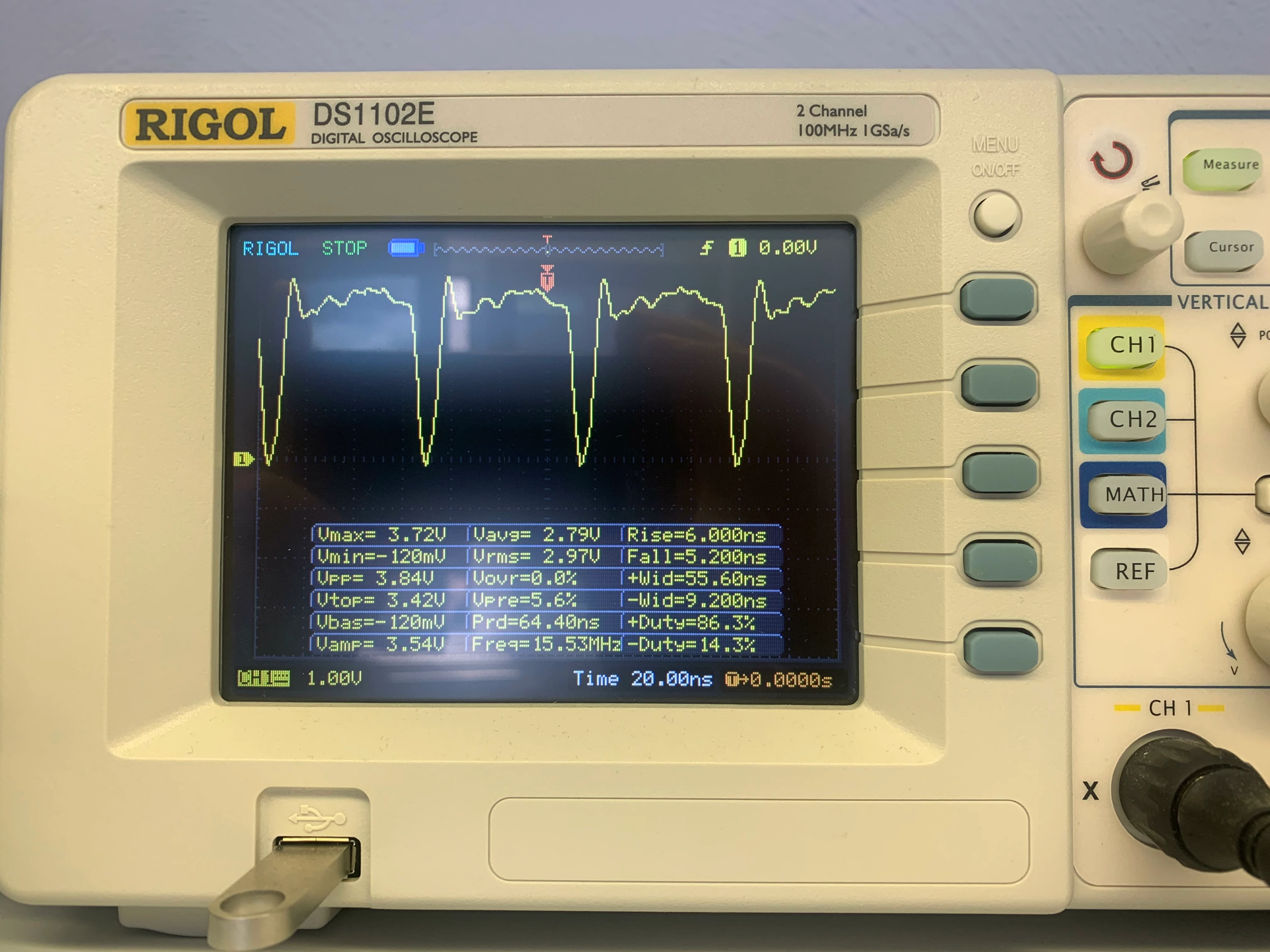
I have obviously misconfigured something, but I'm out of ideas. I read some materials on the topic, will keep researching too, but I was hoping maybe someone could point me in the right direction.
