Associate III
May 6, 2024
Solved

PWM timer frequency double of the expected/calculated

  • May 6, 2024
  • 2 replies
  • 1401 views

Hi,

I'm working with a STM32F439ZI and want to use the PWM outputs of timer3 & timer4. I want to set a frequency of 50Hz (m_dat.fI) as an example. If I calculate it with the formula below, it results in a frequency of 100Hz instead and I'm not sure why, can someone help out?

PSC is set to 27 for both timers. and PCLK1 is at 42MHz

PCLK1Freq = HAL_RCC_GetPCLK1Freq();
TIM3->ARR = (uint32_t)(((double)PCLK1Freq / (double)m_dat.fI) / ((double)TIM3->PSC + 1)) - 1;
TIM4->ARR = (uint32_t)(((double)PCLK1Freq / (double)m_dat.fI) / ((double)TIM4->PSC + 1)) - 1;

    This topic has been closed for replies.
    Best answer by waclawek.jan

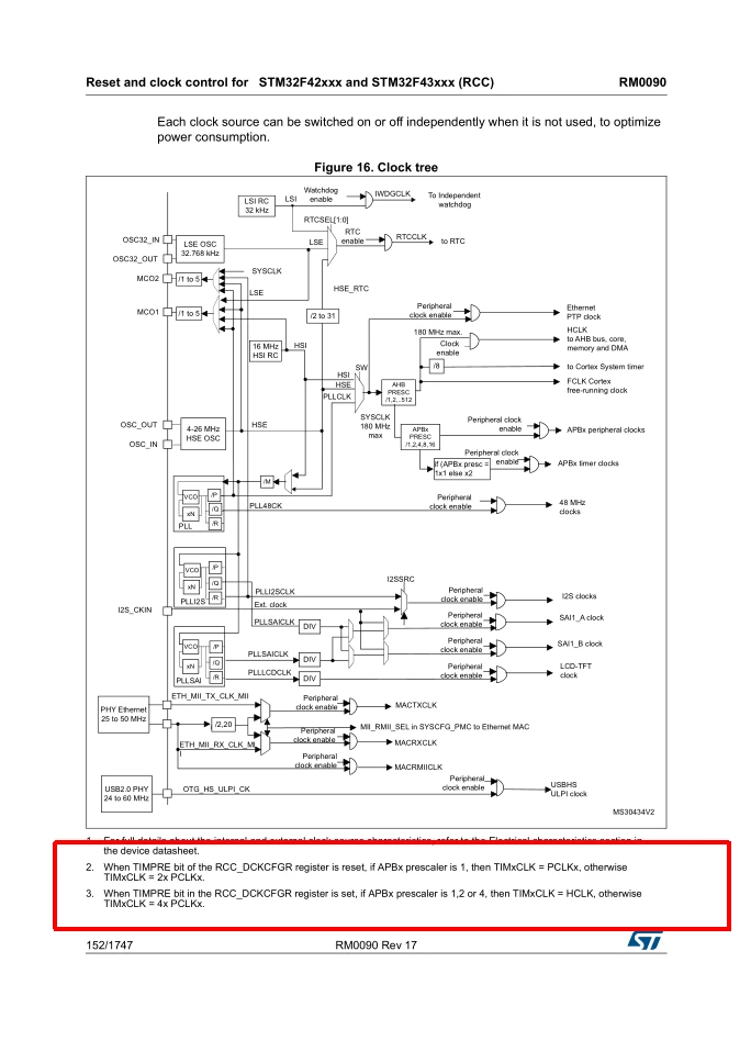
    Timer's clock is twice the APB clock frequency, if APB divider is not 1.

    waclawekjan_0-1715028708943.png


    JW

    2 replies

    waclawek.jan
    waclawek.janBest answer
    Super User
    May 6, 2024

    Timer's clock is twice the APB clock frequency, if APB divider is not 1.

    waclawekjan_0-1715028708943.png


    JW

    Tesla DeLorean
    Guru
    May 6, 2024

    The divider is BYPASSED to allow higher clocking speeds on the slower bus. New STM32 families also allow the clock to come from different internal sources.

    Don't use RMW forms on TIM->SR to clear interrupt flags, just write the inverted bitmask to SR, it will occur in a single cycle, not 4-8 APB cycles.

    Use

    TIM1->SR = ~1; and not TIM1->SR &= ~1;

    Tips, Buy me a coffee, or three.. PayPal Venmo (See Profile) Up vote any posts that you find helpful, it shows what's working..