


Nucleo-H745ZI - OPAMP feeding ADC
I am working on a project that uses an FFT to identify noise in specific frequency windows. Currently, I am configuring the hardware to optimize signal input for this analysis, but I'm facing some challenges with the internal connection settings in the IOC for using the OpAmp and the ADC. Here's an overview of my current situation and the queries I have:
- Hardware Setup: My equipment includes a single coupon from the STEVAL-MIC007V1, which is fitted with an IMP23ABSU analogue microphone. Initially, I connected this microphone directly to the ADC's input and successfully implemented a simple FFT program.
- Proposed Modification: I am considering routing the microphone through an OpAmp before it feeds into the ADC, a technical note said this needed to be done. However, the configuration details in the IOC are a bit unclear to me.
I want to use the non inverting input and the PGA mode and the ADC will be in single ended mode.
I think that the hardware connections should be, ground from microphone to AGND, VDD on microphone to VDDA, output from the microphone to PB0 (OPAMP1_VINP). Do I need to connect anything to VINM?
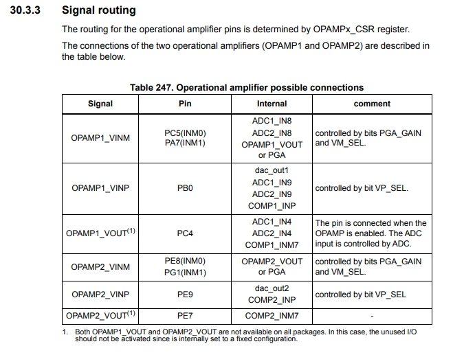
The inverting input, VINM either PC5 or PA7. As I am not using the inverting input I don’t think this matters? unless the ground from the microphone should actually be connected here rather than to the analogue ground pin?
The non inverting input (VINP) is connected to PB0 (this could also be connected internally to ADC1 IN9 but there is no reason to?). This is where I connect the microphone output.
OPAMP1_VOUT is on pin PC4 and I can select ADC1_IN4, I think this should route the OPAMP output directly to the ADC?
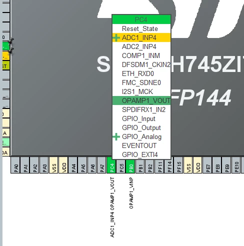
Within IOC if I select OPAMP1 I see PC4 has OPAMP1_VOUT in green and PB0 has OPAMP1_VINP in green.
Moving to ADC1 I can select IN4 as OPAMP1 Output Single-ended and that appears in yellow under the pin allocations.
ADC1 still shows a yellow triangle.
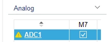
It suggests the following to remove the yellow triangle:
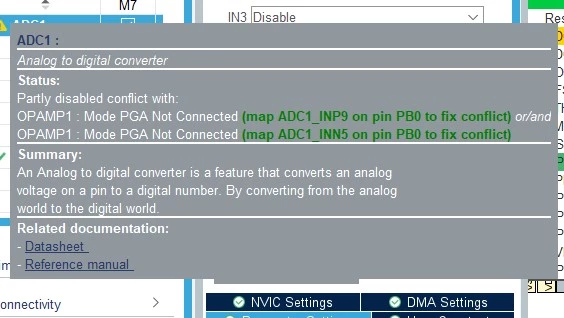
This seems to suggest that I should connect ADC1_INP9 to the same pin as the opamp input? That doesn’t seem correct to me. However if I do select that both are now highlighted in green
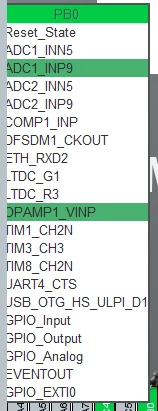
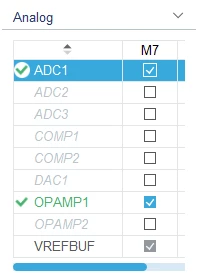
Yet the important one, PC4, OPAMP1_VOUT is green yet the ADC input, ADC_INP4, is still yellow?
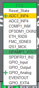
In summary I think this is a question in two parts, how do I connect the OPAMP1_VOUT to ADC_INP4?
Also, from a hardware point of view, what if anything should be connected to VINM