Solved
IOC Pinout View, definition when right click on a pin
Hello,
When I right click on a pin, in the Pinout view of an IOC file, it shows the following:
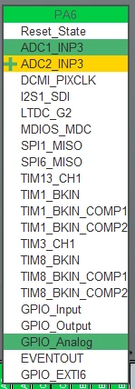
I understand the ADC1_INP3, since that is the intended setting. But what would the yellow ADC2_INP3, with a + next to it, signify? Likewise, what is the reason for the green highlighted GPIO_Analog?
Here is another example:
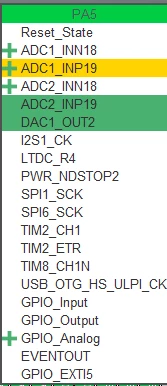
What is the purpose of the 4 "+" signs?, some with color shading and some without. I assume selection of both ADC2_INP19 and DAC1_OUT2, means PA5 is routed to both?
Regards,
Robert