Touby
Associate
September 13, 2023
Solved

HSI48 on STM32F072C8T problem

Hello,

I have a problem with a clock configuration on my STM32F072C8T6. I need the 48MHz clock (HSI48) for the onboard USB communication. I have enabled this via ioc in the clock configuration. Everything looks fine there and no conflict is reported.

Now as soon as I load my program on the STM32, the debug connection breaks as soon as the following line is executed (in the automatically generated SystemClock_Config function --> see attachment) :

__HAL_RCC_HSI48_ENABLE(); (in the stm32f0xx_hal_rcc.c file)

I see that this line only writes the CR2 register with the following command:
RCC->CR2 |= RCC_CR2_HSI48ON;

Unfortunately I can't see which error handler the STM32 goes into, because the debug connection breaks. I have also tried to increase the FLASH latency with the following line, unfortunately without success:
FLASH->ACR |= 0x1;

If I run the program with the 8MHz everything works without problems.

Am I missing something? Can someone help me? Thanks a lot!

    This topic has been closed for replies.
    TDK
    TDKBest answer
    September 20, 2023

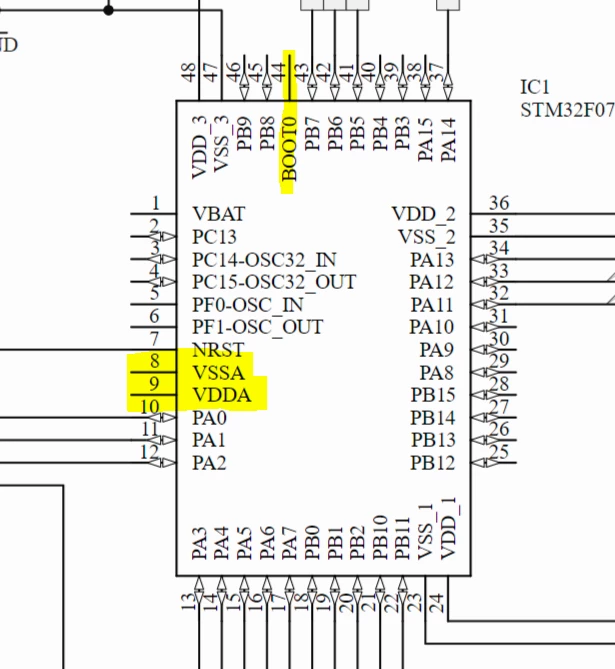
    All VDD/VSS pins need connected to 3V3/GND. Surprised it works at all.

    TDK_0-1695232910257.png

    BOOT0 should generally be pulled down and not left floating.

    "If you feel a post has answered your question, please click ""Accept as Solution""."

    14 replies

    TDK
    September 13, 2023

    Is this a custom board? How is the board being powered? Check NRST and VDD when it fails to help diagnose.

    "If you feel a post has answered your question, please click ""Accept as Solution""."
    Touby
    ToubyAuthor
    Associate
    September 15, 2023

    Thank you for the answer. It is a custom board that provides a regulated 3.3V for the microcontroller.

    About the comments:
    - The 3.3V is stable and permanently present. It is exactly 3.3V.
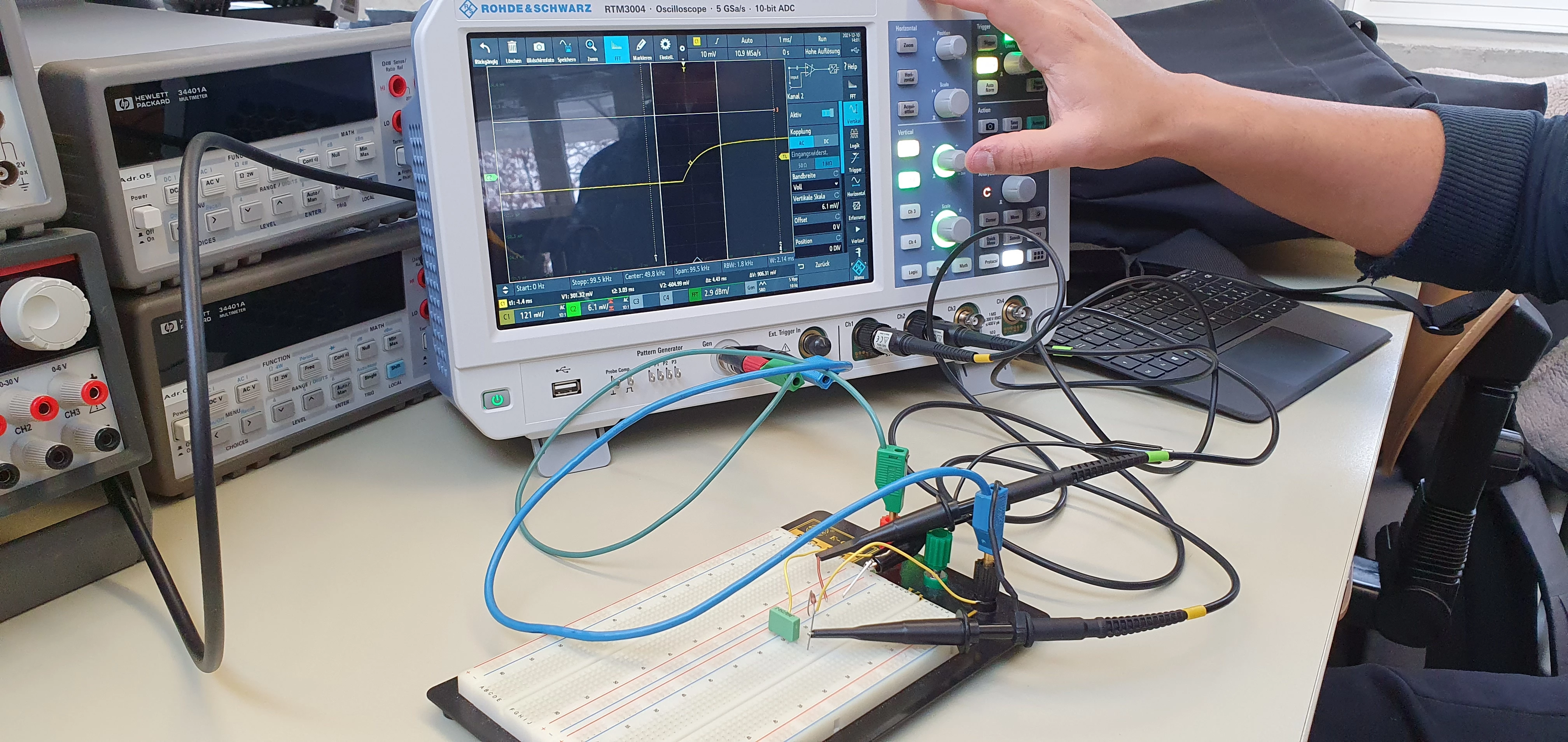
    - The NRST behaves a bit more special. If I disconnect the NRST connection to my ST-Link programmer, I can continue debugging (again up to the mentioned line for the HSI48). However, if I connect my oscilloscope to this pin and want to measure the NRST, I can measure a square wave signal with period = 2.7ms and the ST-Link Programmer loses the connection to the microcontroller. This square wave voltage also occurs when I measure the NRST after said line has been executed.

    Thanks for your help!

    Issamos
    Super User
    September 13, 2023

    Hello @Touby 

    Ensure that you have applied the recommendation in the reference manual: ''

    The HSI48RDY flag in the Clock control register (RCC_CR) indicates if the HSI48 RC is stable or not. At startup, the HSI48 RC output clock is not released until this bit is set by hardware.The HSI48 RC can be switched on and off using the HSI48ON bit in the Clock control register (RCC_CR). This oscillator will be also automatically enabled (by hardware forcing HSI48ON bit to one) as soon as it is chosen as a clock source for the USB and the peripheral is enabled.

    Best regards.

    II

    Touby
    ToubyAuthor
    Associate
    September 15, 2023

    Thank you for the answer. I already tried to set the bits in this register manually with RCC->CR2 |= 0x10000; (as mentioned above). Now I first read the HSI48RDY flag before I set the HSI48On bit (with RCC->CR2 & 0x2000) and this was = 1. So I checked the recommendation in the reference manual.

    Best regards, Touby

    TDK
    September 15, 2023

    > However, if I connect my oscilloscope to this pin and want to measure the NRST, I can measure a square wave signal with period = 2.7ms 

    Okay, so it's resetting itself, probably on the line in question. I don't see why it would do that unless there's a power issue. Are you measuring VDD with a multimeter or an oscilloscope? A multimeter will not show a drop that could be the cause of the reset.

    Is this a genuine chip?

    Check the RCC->CSR flags on startup (and then clear them) to determine the cause of the reset, but probably not much to learn there.

    That's all the ideas I have. Good luck.

    "If you feel a post has answered your question, please click ""Accept as Solution""."
    Touby
    ToubyAuthor
    Associate
    September 17, 2023

    Yes, I understand the point. I also powered the microcontroller via the ST-Link programmer, same behavior. I measured the voltage with the oscilloscope.

    Yes it is the real chip from STM.

    The RCC->CSR flags are all ok. When I look at the register, I see only the two startup resets (POR and NRST). I have also deleted these manually, unfortunately without further success.

    I will continue to search for a solution and if necessary post the solution here.

    TDK
    September 19, 2023

    I've been suggesting it's likely a power issue since post 1. But if it was a power issue, you should have seen VDD dropping on the scope.

    "If you feel a post has answered your question, please click ""Accept as Solution""."
    Touby
    ToubyAuthor
    Associate
    September 20, 2023

    That's true, of course, but I also thought it was an incorrect measurement on my part.

    I could now test it in the lab and got the same result again (with my pricey lab power supply) . As soon as the CR2 register is written (any bits), the microcontroller goes into reset mode. So I checked the addressing of the CR2 register in the CMSIS files. The RCC register is addressed with 0x40021000, so it is correct according to the reference manual. The offset of the CR2 register is 0x34 according to the reference manual. If I now press the macro CR2 via the above described ways to get to the definition (finally in the stm32f072xb.h file), I am shown 5 different options how the CR2 offset is defined. I didn't quite figure it out in the corresponding file.

    Therefore I tried the direct way:

    #define reg_32 *(( volatile unsigned long *) 0x40021034 )
    reg_32 |= 0x10000;

    Even with this I can't write to the CR2 register (I hope the direct addressing is correct, I haven't done it for a while). Now I have no idea, except to put an external oscillator on the board or to throw this microcontroller in the garbage can and try another USB capable microcontroller.

    TDK
    September 20, 2023

    Is there a way in your circuit to measure current drawn from 3.3V? 150mA should be plenty. Could be other errors on the board or in the schematic that are causing the issue.

    Is this a genuine chip?

    Do you have an ST dev board or other known good hardware you could try this code on instead?

    "If you feel a post has answered your question, please click ""Accept as Solution""."
    Touby
    ToubyAuthor
    Associate
    September 20, 2023

    Yes I measured that this morning, it was about 16mA, so 150mA is actually more than enough.

    This is always the point that you do not want to admit. :)
    It could very well be a bug in the design, because I did my software development with the Nucleo-F072RB and everything worked there. Also, this is the first time I've worked with USB, so a mistake may have crept in.

    Attached is my schematic for the microcontroller / USB. Hopefully the comments in German do not disturb. :D

    TDK
    TDKBest answer
    September 20, 2023

    All VDD/VSS pins need connected to 3V3/GND. Surprised it works at all.

    TDK_0-1695232910257.png

    BOOT0 should generally be pulled down and not left floating.

    "If you feel a post has answered your question, please click ""Accept as Solution""."
    Touby
    ToubyAuthor
    Associate
    September 20, 2023

    Thanks for the reply and the help, I didn't know that about BOOT0...I left that open on all previous designs.

    The oversight with the VSS/VDD pins is however quite embarrassing to me. I'm also surprised that the part works without it at all. Will correct that tomorrow and put wire jumpers.

    Sorry for the waste of time.

    Tesla DeLorean
    Guru
    September 20, 2023

    >>I didn't know that about BOOT0...I left that open on all previous designs.

    That can result in indeterminate start-up, depending on how supply rises, and perceived floating voltage in can boot your code or the ROM's

    The Analogue supplies are used for POR, PLL, crystals, etc not just ADC / DAC

    Tips, Buy me a coffee, or three.. PayPal Venmo (See Profile) Up vote any posts that you find helpful, it shows what's working..