

Help Required: Comparator Interrupt based Time measurement
Hello everyone, this is my first post on ST after starting to use the STM32F072RB on the Nucleo Board. It has been only 3 months since I started working with ST parts, so pardon my missing knowledge and misconceptions. This personal project has been stressing me out too much now, so reaching out to all the amazing brains out here for input, help and support. I am new to STM32, ARM Cortex, STM IDE, and STMCube. Please be nice.. :)
So, I am trying to configure a hardware connection between STM32F072 and a chip that works with parasitic power supply allowing power and communication through a single wire. It is similar to OWS but hacky version of it.
Anyway, I have been able to start the transmission to the slave and I am able to get the response through the hardware and I can see that on the oscilloscope as shown in the image below:
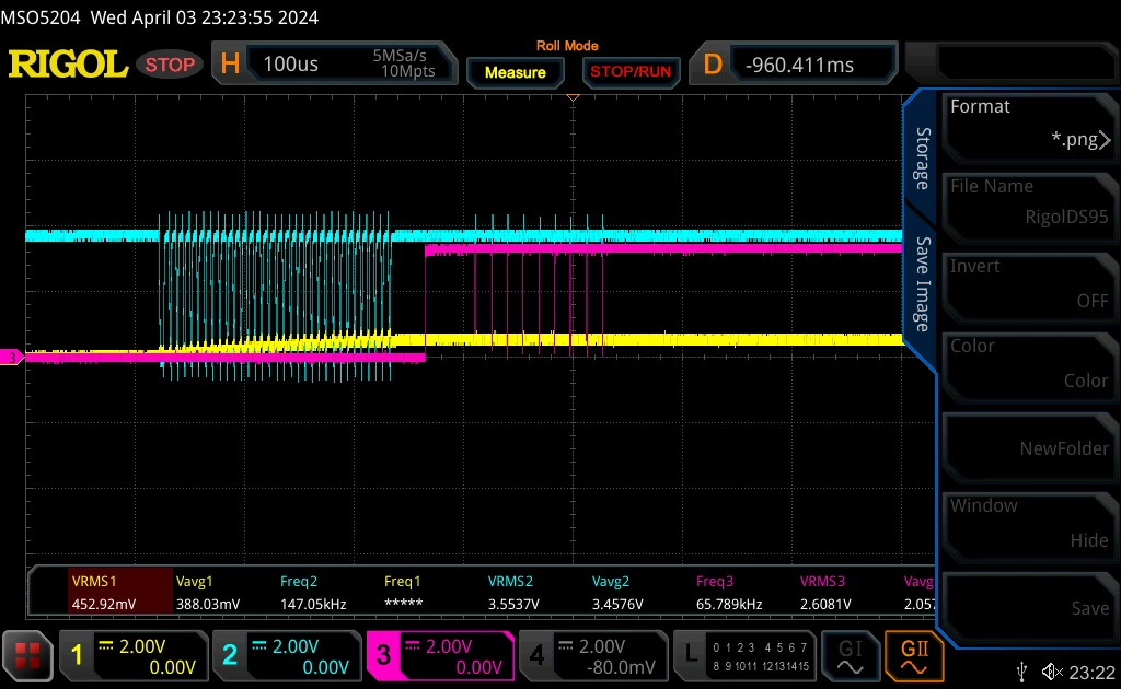
The blue signal is the power line that shows transmission pulses and the small noise like reception pulses. This response is fed into the hardware that also includes the comparator and the pink/purple signal is the response on PA0, that is the forwarded output of COMP1 to the external pin.
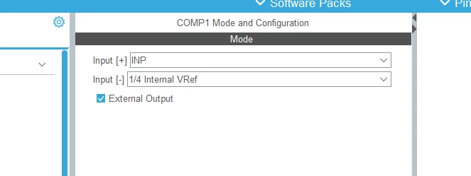
The comparator interrupts are enabled after the transmission is done, before the slave starts to respond. I expect to get 8 bits of data as this is the reset command, and I am getting that on the scope.
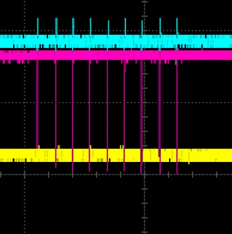
I am not really a professional firmware developer or programmer so I struggle whenever there is complicated code involved. The problem I have here is, I am not able to configure the timer such that it stores and resets the value between the pulses. I have a variable in the code say 'response_interval' which I need to store the time value in microseconds between the two consecutive pulses, I have logically written the conversion part of these intervals to binary values (only need to change the comparison numbers maybe).
Long story short, any step by step help to start the timer once the first pulse is received, store the value in a variable, reset the time count and start again, the values of the time could be stored in an array or converted into binary in real time - (which should not be a problem I hope, fingers crossed).