Associate III
May 2, 2024
Solved

GPIO pins always high on STM32F405RGT6

  • May 2, 2024
  • 4 replies
  • 3956 views

Hello!

I have an STM32F405RGT6 MCU with a custom PCB. I have some trouble with my GPIO pins as they only seem to be high. 


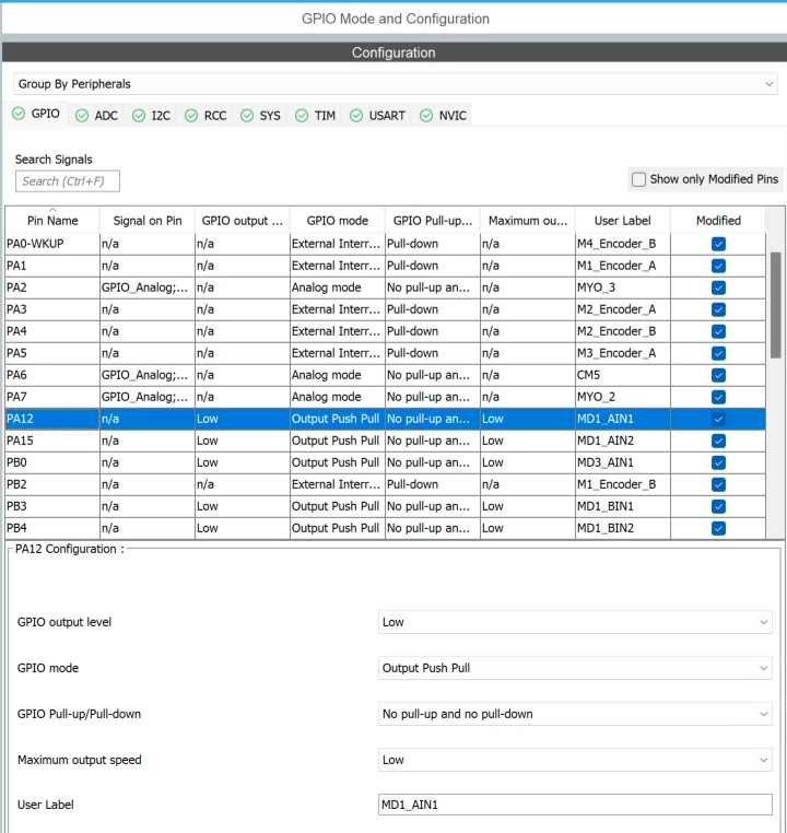
I am using the STM32CubeIDE software and have configured all GPIOs. I having trouble with PA12 and PA15 in particular. See GPIO Mode and Configuration:
mathieusteketee_1-1714673847264.png

I use pin PA12 (MD1_AIN1) and PA15 (MD1_AIN2) for the choose the direction for a DC motor. 

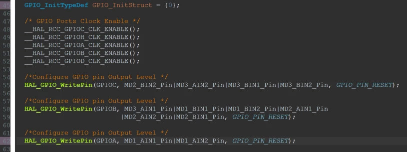
In the "gpio.c" file I have the following code:
mathieusteketee_2-1714674006691.png

As seen both PA12 and PA15 should be RESET = LOW.


Here is the configuration further down in the code: 
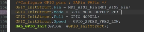
mathieusteketee_3-1714674122590.png


I have tried writing: 

HAL_GPIO_WritePin(GPIOA, MD1_AIN1_Pin|MD1_AIN2_Pin, GPIO_PIN_RESET);

also in the main.c file but did not seem to work. 

I measure with my multimeter between ground and MD1_AIN1 3.3VDC and also between ground and MD1_AIN2. 

See drawing for motor driver:
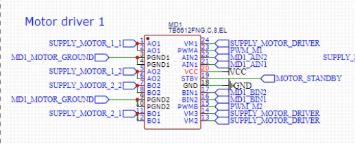
mathieusteketee_4-1714674305061.png


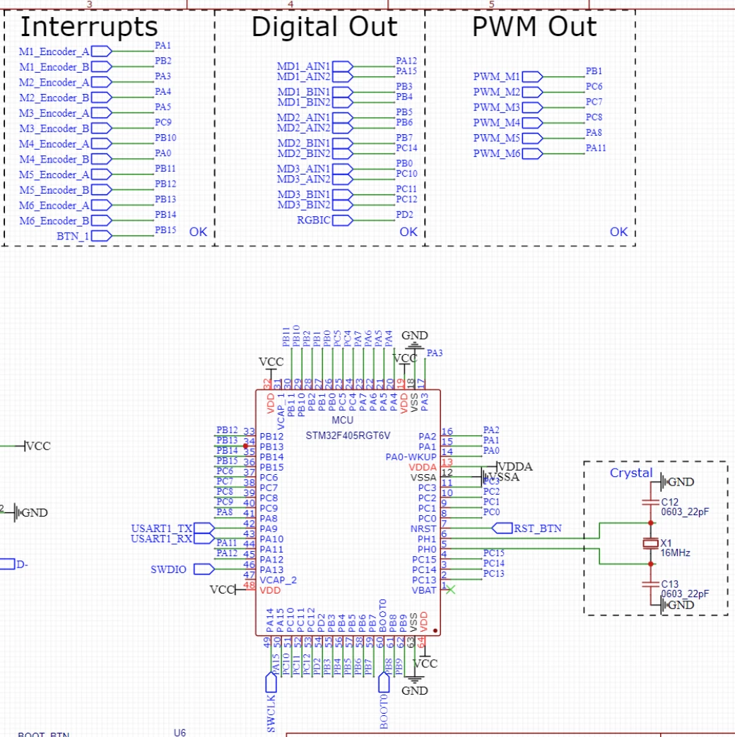
Drawing for MCU (under Digital Out):

mathieusteketee_5-1714674356637.png


Does anybody know why there I have constant 3.3VDC over PA12 and PA15?


Thank you. 



    This topic has been closed for replies.
    Best answer by Tesla DeLorean

    Yes, you need a 2u2 F capacitor on each VCAP, or connect them and use a 4u7 F one

    Part will malfunction without them. Should be able to measure around 1.25 V at these pins.

    PA15 = JTDI

    Does behaviour of pin change if not connected to the debugger / debug pod ?

    4 replies

    Tesla DeLorean
    Guru
    May 2, 2024

    Can you program the part?

    What's going on with the VCAP pins?

    Sure the part orientation is correct?

    Does this persist if you disconnect the motor headers?

    Potential conflicts with SWD/JTAG DP


    Tips, Buy me a coffee, or three.. PayPal Venmo (See Profile) Up vote any posts that you find helpful, it shows what's working..
    Associate III
    May 2, 2024

    Hey @Tesla DeLorean.

    1. Which part are you referring to? I am able to program the MCU yes, I have tested  PB15, which is a button and it works fine.

    2. As you can see in the image below I do not use the VCAP pins. Is this necessary?

    mathieusteketee_0-1714677103942.png

    3. If you mean the MCU orientation, yes it is correct. 

    4. Yes.

    5. Do you mean the Debug Port for SWD/JTAG?

    I am using an ST-Link V2 which is connect via SWD. 

    Here is my debug configuration: 

    mathieusteketee_1-1714677590383.png


    Thank you. 


    Tesla DeLorean
    Tesla DeLoreanBest answer
    Guru
    May 2, 2024

    Yes, you need a 2u2 F capacitor on each VCAP, or connect them and use a 4u7 F one

    Part will malfunction without them. Should be able to measure around 1.25 V at these pins.

    PA15 = JTDI

    Does behaviour of pin change if not connected to the debugger / debug pod ?

    Tips, Buy me a coffee, or three.. PayPal Venmo (See Profile) Up vote any posts that you find helpful, it shows what's working..