MShah.8
Associate
August 2, 2023
Solved

fm0 demodulation using stm32f401re

  • August 2, 2023
  • 7 replies
  • 4375 views

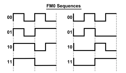
I am attempting to demodulate fm0 modulated signal which is received via gpio on stm32f401re.

MShah8_0-1690977825318.png

What should be the approach to this demodulation? please enumerate the steps i can follow. (ps. ~ the symbol period of fm0 modulated data is 4us)

Some insights to this problem would be much appreciated...:smiling_face_with_smiling_eyes:

    This topic has been closed for replies.
    Best answer by KnarfB
    1. Create a new project with STM32CubeMX or ..IDE.
    2. Configure TIM1 clock source to Internal Clock
    3. Set counter mode Up.
    4. Set Channel1 to Input Capture direct mode.on Both Edges.
    5. TIM1 DMA settings: Add TIM1_CH1 DMA in cyclic mode, leave other defaults.
    6. Generate the code for your IDE.
    7. Start the timer in main.c


     /* USER CODE BEGIN 2 */
     HAL_TIM_IC_Start_DMA(&htim1, TIM_CHANNEL_1, edge_buffer, EDGE_BUFFER_LENGTH);
     /* USER CODE END 2 */


    in main.c at global level add callbacks


    /* USER CODE BEGIN 0 */
    
    #define EDGE_BUFFER_LENGTH 256
    uint16_t edge_buffer[EDGE_BUFFER_LENGTH];
    
    void process(uint16_t edges[], size_t len)
    {
     // compute edge arrival time differences and decide which FM0 cases you have observed
    }
    
    void HAL_TIM_IC_CaptureHalfCpltCallback(TIM_HandleTypeDef *htim)
    {
     HAL_GPIO_WritePin(LD3_GPIO_Port, LD3_Pin, GPIO_PIN_SET);
     process(&edge_buffer[0], EDGE_BUFFER_LENGTH/2);
    }
    
    void HAL_TIM_IC_CaptureCallback(TIM_HandleTypeDef *htim)
    {
     HAL_GPIO_WritePin(LD3_GPIO_Port, LD3_Pin, GPIO_PIN_RESET);
     process(&edge_buffer[EDGE_BUFFER_LENGTH/2], EDGE_BUFFER_LENGTH/2);
    }
    /* USER CODE END 0 */


    Implement the missing parts. Use a debugger early and often, to better understand what the code does. Tune parameters to your needs (buffer size, prescaler,...).

    hth

    KnarfB

    7 replies

    TDK
    August 2, 2023

    It's not easy/straightforward, but it can be done. One way is to create a timer to re-create the clock and then use SPI to receive the data.

    To create the clock, hook up the signal to the external reset, set duty cycle to 50%, set interval to be just over the width of the shortest period. Set channel 1 to provide the clock and have it go from low to high at the mid-point of the internal. Hook up that to SPI_SCK.

    Hook up your signal to to SPI_MISO. Receive data in SPI mode, then do the conversion after it's received. 1010 -> 00, etc. A 4us period might be pushing things, but I imagine it's doable, barely.

    "If you feel a post has answered your question, please click ""Accept as Solution""."
    KnarfB
    Super User
    August 2, 2023

    Alternative ways:

    • Use a free-running timer and EXTI interrupts. The interrupt handler reads the timer counter register and calculates the output bitwise from the observed counter differences.
    • Use a free-running timer's timer channel in input capture mode with cyclic DMA. The input capture shall fire on every edge and the DMA callbacks can be used to evaluate the edge arrival times in larger chunks.

    hth

    KnarfB

    MShah.8
    MShah.8Author
    Associate
    August 3, 2023

    Thanks a lot. If it's not too much trouble, could you share some resources where I can learn how to implement this? I'm new to embedded systems, working as an intern in my third year of B-tech. Some help in this implementation will help me learn better. 

    KnarfB
    KnarfBBest answer
    Super User
    August 3, 2023
    1. Create a new project with STM32CubeMX or ..IDE.
    2. Configure TIM1 clock source to Internal Clock
    3. Set counter mode Up.
    4. Set Channel1 to Input Capture direct mode.on Both Edges.
    5. TIM1 DMA settings: Add TIM1_CH1 DMA in cyclic mode, leave other defaults.
    6. Generate the code for your IDE.
    7. Start the timer in main.c


     /* USER CODE BEGIN 2 */
     HAL_TIM_IC_Start_DMA(&htim1, TIM_CHANNEL_1, edge_buffer, EDGE_BUFFER_LENGTH);
     /* USER CODE END 2 */


    in main.c at global level add callbacks


    /* USER CODE BEGIN 0 */
    
    #define EDGE_BUFFER_LENGTH 256
    uint16_t edge_buffer[EDGE_BUFFER_LENGTH];
    
    void process(uint16_t edges[], size_t len)
    {
     // compute edge arrival time differences and decide which FM0 cases you have observed
    }
    
    void HAL_TIM_IC_CaptureHalfCpltCallback(TIM_HandleTypeDef *htim)
    {
     HAL_GPIO_WritePin(LD3_GPIO_Port, LD3_Pin, GPIO_PIN_SET);
     process(&edge_buffer[0], EDGE_BUFFER_LENGTH/2);
    }
    
    void HAL_TIM_IC_CaptureCallback(TIM_HandleTypeDef *htim)
    {
     HAL_GPIO_WritePin(LD3_GPIO_Port, LD3_Pin, GPIO_PIN_RESET);
     process(&edge_buffer[EDGE_BUFFER_LENGTH/2], EDGE_BUFFER_LENGTH/2);
    }
    /* USER CODE END 0 */


    Implement the missing parts. Use a debugger early and often, to better understand what the code does. Tune parameters to your needs (buffer size, prescaler,...).

    hth

    KnarfB

    KnarfB
    Super User
    August 5, 2023

    edgeTimestamps are absolute values in timer "ticks" (increment periods), you have to calculate the differences manually. The 500 parameter is wrong, it must be the length of the array passed, 100. Cyclic DMA may be overkill, depending on your overall protocol. Typically, there will be some preamble at the beginning of a transfer and you may have some ideas about the transfer length. Then you can start/stop a linear DMA.

    There are more tutorials around for the opposite, generating an arbitrary waveform by a timer & DMA, but the principles are the same.