Associate II
June 18, 2026
Solved

Why 10 kOhm pull-up onto the sdmmc1_ck line?

  • June 18, 2026
  • 3 replies
  • 55 views

Hi!

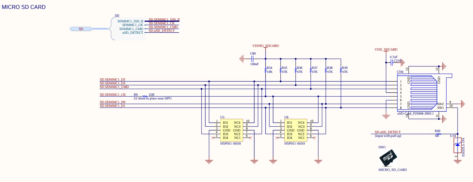
I wonder why ST have chosen to implement a 10 kOhm pull-up (R34) on the clock line of the SD-card?

I have seen this on the STM32MP257F-DK board from ST.

Normally, you chould not have a 10 kOhm pull-up on the clock signal, only the other data/command signals.

That’s the reason why the EMI filters for the SD-card e.g ST products EMIF06-HMC02F2 and EMIF06-MSD02N16 does not any pull-up onto the clock signal.


Best answer by ZAKARIA_C1

Hello ​@Windows,

No, the internal pull-ups are NOT initialized automatically they are in a high-impedance (floating) state by default at power-up, before the BootROM or early bootloader configures the GPIOs.
For the STM32MP2 series. The pull-up configuration must be done explicitly, either via:

  • External resistors on the PCB (recommended for reliable boot)

  • Device tree configuration using bias-pull-up in the pin control node for signals initialized later in the boot chain (e.g., D1–D3 when switching from 1-bit to 4-bit mode)

I think AN5489 is actually correct the reason no internal pull-up is shown in the figure is simply because an external pull-up is already depicted in the schematic diagram.

Thank you.
Best regards,
Zakaria

3 replies

ST Employee
June 25, 2026

Hello ​@Windows,

During system power-up or low-power states, the GPIOs of the STM32MP25 default to a high-impedance (floating) state before the BootROM or early bootloader firmware initializes them.

If the clock line is left floating during this critical boot phase, electromagnetic interference (EMI) or board noise could induce spurious voltage transitions.

The SD card controller might misinterpret these random fluctuations as valid clock edges, potentially causing the card to enter an undefined or faulty state before the system is even ready to communicate with it.

By adding a weak pull-up (or sometimes a pull-down) resistor, the reference design ensures the clock line remains at a stable, defined logic level when the processor is not actively driving the bus.

For production designs, adding the clock pull-up is generally optional. If your system firmware initializes the SDMMC peripheral GPIOs rapidly and you do not frequently hot-swap the SD card, the transient floating state may never cause a practical issue. However, keeping the resistor pad on the PCB as a "Do Not Fit" (DNF) component is a good practice, as it provides a fallback if you encounter initialization issues during your EMI validation testing.

Best Regards,
Zakaria

In order to give better visibility on the answered topics, please click on 'Best answer' on the reply which solved your issue or answered your question.
WindowsAuthor
Associate II
June 25, 2026

Thank you for your answer ​@ZAKARIA_C1 

One more question:  Are the internal pull-ups for CLK, CMD, D0, D1, D2 and D3 initialized automatically or does it need to be done internally?


By the way, if CLK have an internal pull-up. Then the getting started manual AN5489 for the STM32MP2, figure 27, need to be corrected.

ZAKARIA_C1Best answer
ST Employee
June 29, 2026

Hello ​@Windows,

No, the internal pull-ups are NOT initialized automatically they are in a high-impedance (floating) state by default at power-up, before the BootROM or early bootloader configures the GPIOs.
For the STM32MP2 series. The pull-up configuration must be done explicitly, either via:

  • External resistors on the PCB (recommended for reliable boot)

  • Device tree configuration using bias-pull-up in the pin control node for signals initialized later in the boot chain (e.g., D1–D3 when switching from 1-bit to 4-bit mode)

I think AN5489 is actually correct the reason no internal pull-up is shown in the figure is simply because an external pull-up is already depicted in the schematic diagram.

Thank you.
Best regards,
Zakaria

In order to give better visibility on the answered topics, please click on 'Best answer' on the reply which solved your issue or answered your question.
WindowsAuthor
Associate II
June 29, 2026

Thank you ​@ZAKARIA_C1 

I will go with the Device Tree Configuration method. No external pull-ups applied (except for the CLK line).

Yes, the EMI-filter for SDR50 have internal pull-ups. But SDR50 is quite slow technology compared for the modern SDR104.