
How to maintain DCACHE coherency for DMA on STM32MP2xx Cortex®-M33
Summary
This article explains how to maintain data cache coherency on STM32MP2xx Cortex®-M33 when DCACHE is enabled and DMA shares buffers with the CPU. It explains when DCACHE maintenance is required, how the requirement depends on the memory protection unit (MPU) and linker memory layout. Finally, how to use the STM32MP2xx hardware abstraction layer (HAL) APIs in a typical DMA transfer.
Introduction
This article is intended for embedded software engineers who use STM32MP2xx Cortex®-M33 with DMA and DCACHE enabled.
DCACHE improves performance, but the CPU view of a buffer can differ from the memory view that DMA uses. If DCACHE maintenance is missing, DMA can read stale data from memory, or the CPU can read stale data from the cache after DMA completes.In some cases, a dirty cache line can also be written back to memory during an inbound DMA transfer and overwrite data just written by DMA.
In addition, cache maintenance operates on cache lines, not on individual bytes. Therefore, DMA buffers located in cacheable memory must also be designed with cache-line alignment in mind.
1. Understand the DCACHE coherency policy
On STM32MP2xx Cortex®-M33, DMA coherency depends on two factors:
- Whether the buffer is in a cacheable or noncacheable region.
- Whether the CPU or DMA updates the buffer first.
DCACHE maintenance is required only for cacheable regions. Accesses to noncacheable regions bypass the cache and do not require clean or invalidate operations.
In practice, the coherency policy is as follows:
- If a shared buffer is in a noncacheable region, no DCACHE maintenance is required.
- If a shared buffer is in a cacheable region, software must maintain coherency explicitly.
For cacheable DMA buffers, apply the following rules:
- CPU writes to the buffer, then DMA reads the buffer: clean.
- DMA writes to the buffer, then the CPU reads the buffer: invalidate before DMA start and invalidate again after DMA completion.
These same rules also apply to DMA control structures stored in memory, such as descriptors or linked-list nodes, when they are in a cacheable region
This usage aligns with the HAL driver notes:
- HAL_DCACHE_CleanByAddr() is used when the CPU updates a buffer before a peripheral such as DMA uses it.
- HAL_DCACHE_InvalidateByAddr() is used when a peripheral such as DMA updates a buffer before the CPU reads it.
Why two invalidates are needed for DMA-written buffers
For a cacheable destination buffer, the two invalidates serve different purposes:
- Invalidate before DMA start: prevents any dirty cache line covering the destination buffer from being evicted during the DMA transfer and writing stale CPU data back to memory.
- Invalidate after DMA completion: removes any stale cache lines so the CPU fetches the data updated by DMA from memory.
So for an inbound DMA transfer into a cacheable buffer, the correct rule is:
- invalidate before DMA
- invalidate after DMA
2. Check whether the buffer is in a cacheable region
DCACHE maintenance applies only to cacheable memory regions.
In the provided MPU configuration, the application defines one cacheable region and one noncacheable region.
Example of cacheable MPU attributes:
/* write back, read and write allocate */
   MPU_Attributes_InitStruct.Attributes = INNER_OUTER(MPU_WRITE_BACK | MPU_NON_TRANSIENT | MPU_RW_ALLOCATE);
   MPU_Attributes_InitStruct.Number = MPU_ATTRIBUTES_NUMBER0;
   HAL_MPU_ConfigMemoryAttributes(&MPU_Attributes_InitStruct);
   /* DCACHE */
   MPU_InitStruct.AccessPermission = MPU_REGION_ALL_RW;
   MPU_InitStruct.Enable = MPU_REGION_ENABLE;
   MPU_InitStruct.AttributesIndex = MPU_ATTRIBUTES_NUMBER0;
   MPU_InitStruct.DisableExec= MPU_INSTRUCTION_ACCESS_DISABLE;
   MPU_InitStruct.IsShareable = MPU_ACCESS_INNER_SHAREABLE;
   MPU_InitStruct.BaseAddress =  0x80A00000;
   MPU_InitStruct.LimitAddress = 0x80DFFC00;
   MPU_InitStruct.Number = MPU_REGION_NUMBER1;
   HAL_MPU_ConfigRegion(&MPU_InitStruct);
Example of noncacheable MPU attributes:
MPU_Attributes_InitStruct.Attributes = INNER_OUTER(MPU_NOT_CACHEABLE);
   MPU_Attributes_InitStruct.Number = MPU_ATTRIBUTES_NUMBER1;
   HAL_MPU_ConfigMemoryAttributes(&MPU_Attributes_InitStruct);

   MPU_InitStruct.AccessPermission = MPU_REGION_ALL_RW;
   MPU_InitStruct.Enable = MPU_REGION_ENABLE;
   MPU_InitStruct.AttributesIndex = MPU_ATTRIBUTES_NUMBER1;
   MPU_InitStruct.DisableExec= MPU_INSTRUCTION_ACCESS_DISABLE;
   MPU_InitStruct.IsShareable = MPU_ACCESS_INNER_SHAREABLE;
   MPU_InitStruct.BaseAddress =  0x81200000;
   MPU_InitStruct.LimitAddress = 0x812FFFFF;
   MPU_InitStruct.Number = MPU_REGION_NUMBER2;
   HAL_MPU_ConfigRegion(&MPU_InitStruct);
The linker file defines the related memory regions as follows:
MEMORY
{
  NS_VECTOR_TBL (xrw)   : ORIGIN = 0x80100000,  LENGTH = 0x00000600
  RAM           (rx)    : ORIGIN = 0x80A00000,  LENGTH = 4M
  IPC_SHMEM_1   (rw)    : ORIGIN = 0x81200000,  LENGTH = 1M - _virtio_shmem_size
  VIRTIO_SHMEM  (rw)    : ORIGIN = ORIGIN(IPC_SHMEM_1)+LENGTH(IPC_SHMEM_1), LENGTH = _virtio_shmem_size

}
This configuration means that:
- RAM at 0x80A00000 is in the cacheable DCACHE region.
- IPC_SHMEM_1 and VIRTIO_SHMEM at 0x81200000 are in the noncacheable region.
2.1 Example from this project
Normal application buffers are typically placed in .data or .bss. In the linker file, both sections are mapped to RAM:
/* Initialized data sections into "RAM" Ram type memory */
  .data : ALIGN(LINKER_DEFAULT_ALIGNMENT)
  {
    _sdata = .;        /* create a global symbol at data start */
    *(.data)           /* .data sections */
    *(.data*)          /* .data* sections */

    _edata = .;        /* define a global symbol at data end */
    . = ALIGN(LINKER_DEFAULT_ALIGNMENT);
  } >RAM

  /* Uninitialized data section into "RAM" Ram type memory */
  .bss : ALIGN(LINKER_DEFAULT_ALIGNMENT)
  {
    /* This is used by the startup in order to initialize the .bss section */
    _sbss = .;         /* define a global symbol at bss start */
    __bss_start__ = _sbss;
    *(.bss)
    *(.bss*)
    *(COMMON)

    _ebss = .;         /* define a global symbol at bss end */
    __bss_end__ = _ebss;
    . = ALIGN(LINKER_DEFAULT_ALIGNMENT);
  } >RAM
As a result, buffers such as:
__attribute__((aligned(32))) uint32_t aSRC_Buffer1[BUFFER1_SIZE];
__attribute__((aligned(32))) uint32_t aDST_Buffer1[BUFFER1_SIZE];
are placed in RAM, which is cacheable in this project. When DMA shares these buffers, DCACHE maintenance is required.
By contrast, IPC_SHMEM_1 and VIRTIO_SHMEM are already defined as shared memory regions and are mapped by the MPU as noncacheable. For these regions, DCACHE maintenance is not required.
Important: if a DMA buffer is placed in a cacheable region, software must also ensure that the buffer does not share cache lines with unrelated data. This is typically achieved by using cache-line aligned buffers and a buffer size, or maintained range, that covers the full cache-line (32 bytes) envelope.
3. Use the relevant HAL APIs
The STM32MP2xx HAL provides the following APIs:
- HAL_DCACHE_CleanByAddr(): writes back dirty cache lines for an address range to memory.
- HAL_DCACHE_InvalidateByAddr(): invalidates cache lines for an address range.
- HAL_DCACHE_CleanInvalidByAddr(): writes back and invalidates cache lines for an address range.
For DMA coherency, the main functions are:
HAL_DCACHE_CleanByAddr() and HAL_DCACHE_InvalidateByAddr().
3.1 HAL_DCACHE_CleanByAddr()
Use this function when the CPU updates a buffer and DMA must read it.
HAL_DCACHE_CleanByAddr(DCACHE_HandleTypeDef *hdcache, const uint32_t *const pAddr, uint32_t dSize)
Parameters:
- hdcache: pointer to the DCACHE handle.
- pAddr: start address of the region to clean.
- dSize: size of the region to clean, in bytes.
3.2 HAL_DCACHE_InvalidateByAddr()
Use this function when DMA updates a buffer and the CPU must read it.
HAL_DCACHE_InvalidateByAddr(DCACHE_HandleTypeDef *hdcache, const uint32_t *const pAddr, uint32_t dSize);
Parameters:
- hdcache: pointer to the DCACHE handle.
- pAddr: start address of the region to invalidate.
- dSize: size of the region to invalidate, in bytes.
Note about address-based cache maintenance
These APIs operate on cache lines, not on individual bytes. Therefore, when using them on DMA buffers in cacheable memory:
- the buffer start address should be aligned to the cache-line size
- the maintained size, or maintained envelope, should cover whole cache lines
- Otherwise, cache maintenance may affect adjacent data sharing the same cache line.
4. Clean DCACHE before DMA reads a CPU-updated buffer
If the CPU prepares a source buffer and DMA reads it, clean the corresponding cache lines before DMA starts. This function writes back dirty cache lines to memory so that DMA reads the latest data. In the STM32MP2xx DMA linked-list example, the source buffers are cleaned before the transfer starts:
 /* Flushing the cache before DMA transfer */
  HAL_DCACHE_CleanByAddr(&hdcache, aSRC_Buffer1, BUFFER1_SIZE* sizeof(uint32_t));
  HAL_DCACHE_CleanByAddr(&hdcache, aSRC_Buffer2, BUFFER2_SIZE* sizeof(uint32_t));
  HAL_DCACHE_CleanByAddr(&hdcache, aSRC_Buffer3, BUFFER3_SIZE* sizeof(uint32_t));
 /* Configure the source, destination and buffer size DMA fields and Start DMA Channel/Stream transfer */
  /* Enable All the DMA interrupts */
  if (HAL_DMAEx_List_Start_IT(&handle_HPDMA3_Channel13) != HAL_OK)
  {
    Error_Handler();
  }
If this step is skipped, DMA can transfer outdated buffer content.
5. Invalidate DCACHE before and after DMA writes a buffer
If DMA writes a destination buffer and the CPU reads it afterward, invalidate the corresponding cache lines after DMA completes. This function removes stale cached data so that the CPU reloads the updated content from memory.
In the STM32MP2xx DMA linked-list example, the destination buffers are invalidated in the transfer-complete callback:
/* Invalidate destination buffers before DMA writes them */
  HAL_DCACHE_InvalidateByAddr(&hdcache, aDST_Buffer1, BUFFER1_SIZE * sizeof(uint32_t));
  HAL_DCACHE_InvalidateByAddr(&hdcache, aDST_Buffer2, BUFFER2_SIZE * sizeof(uint32_t));
  HAL_DCACHE_InvalidateByAddr(&hdcache, aDST_Buffer3, BUFFER3_SIZE * sizeof(uint32_t));

/* Configure the source, destination and buffer size DMA fields and Start DMA Channel/Stream transfer */
  /* Enable All the DMA interrupts */
  if (HAL_DMAEx_List_Start_IT(&handle_HPDMA3_Channel13) != HAL_OK)
  {
    Error_Handler();
  }

  /* Wait for end of transmission or an error occurred */
  while ((TransferCompleteDetected == 0) && (TransferErrorDetected == 0U));

  /* Check DMA error */
  if (TransferErrorDetected == 1U)
  {
    Error_Handler();
  }

  /* Check destination buffer1 */
  if (Buffercmp((uint8_t*)aSRC_Buffer1, (uint8_t*)aDST_Buffer1, (BUFFER1_SIZE * 4U)) != 0U)
  {
    Error_Handler();
  }

  /* Check destination buffer2 */
  if (Buffercmp((uint8_t*)aSRC_Buffer2, (uint8_t*)aDST_Buffer2, (BUFFER2_SIZE * 4U)) != 0U)
  {
    Error_Handler();
  }

  /* Check destination buffer3 */
  if (Buffercmp((uint8_t*)aSRC_Buffer3, (uint8_t*)aDST_Buffer3, (BUFFER3_SIZE * 4U)) != 0U)
  {
    Error_Handler();
  }
static void TransferComplete(DMA_HandleTypeDef *hdma)
{
  /* Invalidating cache lines after DMA transfer */
  HAL_DCACHE_InvalidateByAddr(&hdcache, aDST_Buffer1, BUFFER1_SIZE * sizeof(uint32_t));
  HAL_DCACHE_InvalidateByAddr(&hdcache, aDST_Buffer2, BUFFER2_SIZE * sizeof(uint32_t));
  HAL_DCACHE_InvalidateByAddr(&hdcache, aDST_Buffer3, BUFFER3_SIZE * sizeof(uint32_t));
  TransferCompleteDetected = 1U;
}
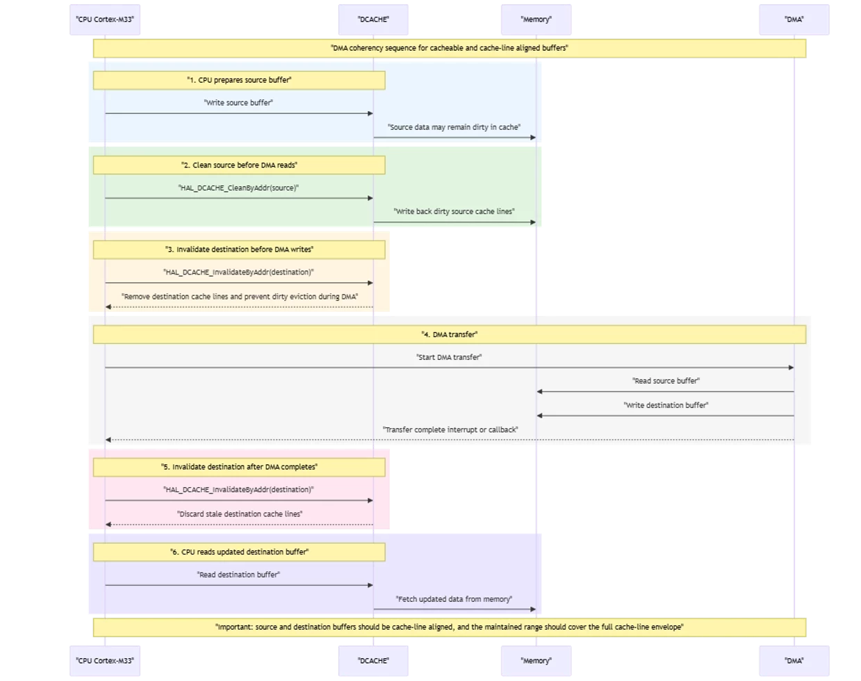
In a memory-to-memory DMA example, this sequence means:
- Clean the source buffer before DMA starts.
- Invalidate the destination buffer after DMA completes.
The following diagram summarizes the recommended DCACHE maintenance sequence for a DMA transfer using cacheable buffers on STM32MP2xx Cortex®-M33.
6. Common mistakes to avoid
Avoid the following common mistakes:
- Forgetting to clean a source buffer before DMA reads it.
- Forgetting that DMA descriptors, linked-list nodes, or other memory-based DMA control structures may also require DCACHE maintenance when placed in a cacheable region
- Forgetting to invalidate a destination buffer before DMA starts when the destination is cacheable
- Forgetting to invalidate a destination buffer after DMA completes before the CPU reads it
- Assuming that a buffer in a noncacheable region still needs DCACHE maintenance.
- Using DMA buffers that are not aligned to cache-line boundaries.
Conclusion
On STM32MP2xx Cortex®-M33, DCACHE coherency for DMA follows a simple policy:
- Buffers in noncacheable regions do not require DCACHE maintenance.
- Buffers in cacheable regions require explicit clean or invalidate operations.
For information about how to enable and disable caches on STM32MP2xx CM33, refer to the ST wiki:
ST wiki: How to add ICACHE and DCACHE support to your applications
