

Associate III
July 6, 2026
Solved

Unable to Connect to BlueNRG-332AC via SWD

  • July 6, 2026
  • 12 replies
  • 145 views

Hi ,

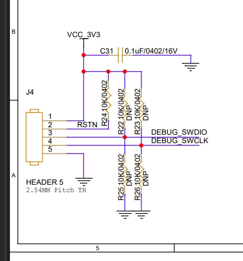
I'm currently working with a BlueNRG-332AC and am unable to establish an SWD connection for programming/debugging.

Hardware Checks

  • Verified the SWD header continuity – all connections are OK.

  • Tried swapping SWDIO and SWCLK to rule out wiring issues, but it made no difference.

  • The target board is powered.

Voltage Measurements on SWD Header

Pin Measured Voltage
Pin 1 (VCC) 3.3 V
Pin 2 3.3 V
Pin 3 (SWDIO) 3.3 V
Pin 4 (SWCLK) 0 V
GND 0 v

Software Tried

  • BlueNRG ST-Link Utility

  • RF Flasher Utility

BlueNRG ST-Link Utility Log

18:29:21 : Can not connect to target!
If you're trying to connect to a low frequency application, please select a lower SWD Frequency mode from Target->Settings menu.

18:29:22 : No target connected

18:29:32 : Can not connect to target!
Please select "Connect with Pre-Reset" mode from Target->Settings menu and try again.
If you're trying to connect to a low frequency application, please select a lower SWD Frequency mode from Target->Settings menu.

18:29:33 : No target connected

RF Flasher Log

****** FLASH READ OPERATION ******

Read of n.1 device connected by SWD (ST-Link, CMSIS-DAP, J-Link)

18:30:09.263: Waiting device to read (device connected by ST-Link) -> FAILED.
(It's not possible to connect to the device)

What I've Already Tried

  • Verified SWD wiring and continuity.

  • Checked target power supply.

  • Swapped SWDIO and SWCLK connections.

  • Tried connecting using both Normal and Connect Under Reset (Pre-Reset) modes.

  • Reduced the SWD frequency.

Has anyone encountered a similar issue with the BlueNRG-332AC? Is there anything else I should verify, such as boot configuration, reset circuitry, SWD pin configuration, or device security state?

NOTE: Since i have only swd header to connect since UART connection also not possible
 

Any suggestions would be greatly appreciated. Thanks!

Best answer by Laurent LOUAZON

Hello,

Schematics
I see two big problems
- C27 must be 220nF and not 10uF
It is decoupling cap for internal LDO voltage that creates 1.2V core voltage.
It might happen internal LDO is not stable with 10uF. Have you checked Vcap level is 1.2V?
- C23 and C24 are too high.
Those caps are here to center LSE frequency. 
I do not know load cap of 32kHz xtal selected, but if using a 6pF Xtal, C23 and C24 will be around 10pF (twice Xtal load cap minus parasitics). In any case 100nF is too high. 
It might happen LSE is not functional.

Other comments (to consider but that are not related to problem you are facing)
- What is L1 value? It should be a 10uH with lows ESR and 100mA min as rating current.
- R24 is not needed (reset in internally pulled up) but a 100nF decoupling cap is recommended
- I also recommend a test point on PA10.
If an application is running inside BlueNRG and low power is used, SWD interface cannot be accessed.
It is then needed to use PA10 pin for forcing boot mode. See below wiki page 

STM32WB0 device debug and access in low-power mode - stm32mcu

- See a HW reference design for BluenRG-332 (also named STM32WB05) with below link

https://www.st.com/en/evaluation-tools/stdes-wb05kv2ld.html#cad-resources

- RF matching/filtering implemented is not correct.
See the example in reference design or  AN5526.


Please let me know if this helps 

Laurent
 

12 replies

Peter BENSCH
ST Technical Moderator
July 6, 2026

Could you please include a photo of your hardware showing the SWD connection to your computer?
If it is an ST-LINK/V2 in a plastic housing, please also include a photo of the back.

Regards
/Peter

In order to give better visibility on the answered topics, please click on Accept as Solution on the reply which solved your issue or answered your question.
Andrew Neil
Super User
July 6, 2026

If it is an ST-LINK/V2 in a plastic housing, please also include a photo of the back.


@avinpat_8 - I think what Peter’s hinting at is:


A complex system that works is invariably found to have evolved from a simple system that worked.A complex system designed from scratch never works and cannot be patched up to make it work.
avinpat_8Author
Associate III
July 14, 2026

Hi,

I have attached the images. The BlueNRG-332AC board is powered through a USB Type-C cable, and I am measuring 3.3 V at the J4 VCC pin. The ST-LINK/V2 programmer is also powered through USB and is connected correctly.

Please review the setup shown in the attached images.

avinpat_8Author
Associate III
July 7, 2026

Hi,

I have attached the images. The BlueNRG-332AC board is powered through a USB Type-C cable, and I am measuring 3.3 V at the J4 VCC pin. The ST-LINK/V2 programmer is also powered through USB and is connected correctly.

Please review the setup shown in the attached images.

avinpat_8Author
Associate III
July 7, 2026

Hi,

I have attached the images. The BlueNRG-332AC board is powered through a USB Type-C cable, and I am measuring 3.3 V at the J4 VCC pin. The ST-LINK/V2 programmer is also powered through USB and is connected correctly.

And also I have observed one thing the pA10 pin is at high is this causing issue

Please review the setup shown in the attached images.


Laurent LOUAZON
ST Employee
August 20, 2026

Hello,
Can you share your entire schematics?
Regards
Laurent

avinpat_8Author
Associate III
August 20, 2026

Hi @ Laurent

I have attached schematic please take a look at it once and let me know as soon as possible since it was pending from long time.

Laurent LOUAZON
Laurent LOUAZONBest answer
ST Employee
August 20, 2026

Hello,

Schematics
I see two big problems
- C27 must be 220nF and not 10uF
It is decoupling cap for internal LDO voltage that creates 1.2V core voltage.
It might happen internal LDO is not stable with 10uF. Have you checked Vcap level is 1.2V?
- C23 and C24 are too high.
Those caps are here to center LSE frequency. 
I do not know load cap of 32kHz xtal selected, but if using a 6pF Xtal, C23 and C24 will be around 10pF (twice Xtal load cap minus parasitics). In any case 100nF is too high. 
It might happen LSE is not functional.

Other comments (to consider but that are not related to problem you are facing)
- What is L1 value? It should be a 10uH with lows ESR and 100mA min as rating current.
- R24 is not needed (reset in internally pulled up) but a 100nF decoupling cap is recommended
- I also recommend a test point on PA10.
If an application is running inside BlueNRG and low power is used, SWD interface cannot be accessed.
It is then needed to use PA10 pin for forcing boot mode. See below wiki page 

STM32WB0 device debug and access in low-power mode - stm32mcu

- See a HW reference design for BluenRG-332 (also named STM32WB05) with below link

https://www.st.com/en/evaluation-tools/stdes-wb05kv2ld.html#cad-resources

- RF matching/filtering implemented is not correct.
See the example in reference design or  AN5526.


Please let me know if this helps 

Laurent