LLr.1
Associate III
January 24, 2022
Solved

Sigfox with STM32WL55: Higher consumption in stop mode than specified in AN5480

  • January 24, 2022
  • 17 replies
  • 7571 views

Hello,

I want to check the low consumption in stop2 mode. I use directly the Sigfox_PushButton example of cubeWL

Page 71/79 of the AN5480 (Rev4 - July 2020) :

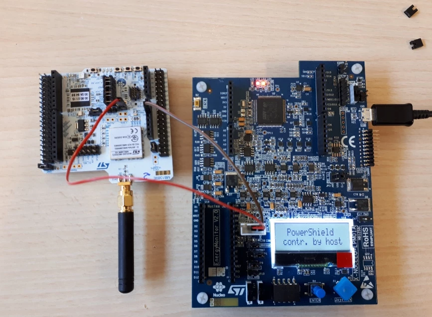
0693W00000JN51fQAD.pngI use the X_NUCLEO-LPM01A to measure the consumption in stop mode. With this setup:

0693W00000JN56BQAT.pngI supply the MCU through I_SoC (JP1) (at 3.3V)

I remove JP7 to remove LED5.

I remove STLK jumper (as shown in UM2592 P.22)

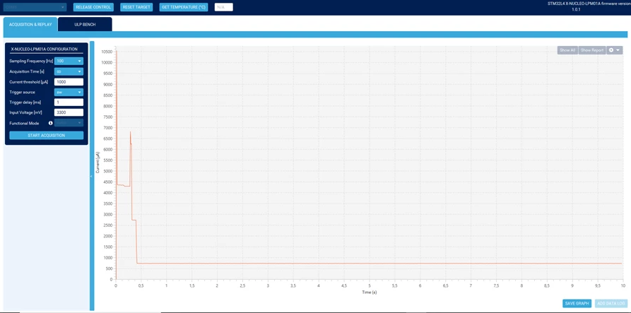
I measure : 725uA !!!0693W00000JN57iQAD.png 

How in practice to measure these 2uA ?

Thank you

Best regards

This topic has been closed for replies.
Best answer by Bruno_ST

Hello @LLr.1​ 

So, i confirm my expectations...

If you power the nucleo with USB (STLINK) + JP1 via X_NUCLEO-LPM01A, you get effectively the 2uA in STOP2 mode in the Sigfox example.

If you only power the nucleo via JP1 (X_NUCLEO-LPM01A) + remove all JP7 jumpers (so performs the measurement like shown in you first picture with JP7 removed) you get an overcurrent because of VDD_APP not beeing supplied (due to the RF switch U3). If you keep SB32 and solder a jumper on JP9 then disconnecting JP9 and you get your 2uA back (but RF is not functional anymore).

So yes, i agree with you best choice is to solder JP9 and supply both JP1 + JP9 external with X_NUCLEO-LPM01A.

Another remark, i have noticed that putting the fingers around JP7 create can also create overconsumptions. It is expected as you left in a dangling state VCP_RX & VCP_TX. So to keep traces functional and avoid extra consumptions due to noise, pull-up PA2/PA3 (GPIO_InitStruct.Pull = GPIO_PULLUP;)

Do you confirm it is now ok on you side ?

BR,

Bruno

PS: Please select as best answer to improve stcommunity experience

17 replies

ST Employee
January 28, 2022

Hello @LLr.1​ 

In the above measurement, you have to power-up the LDO (component U2) Figure 10. STM32WL Nucleo-64 board power tree because 3.3V is needed to supply the VDD_APP.

If you want to only supply the board through X_NUCLEO-LPM01A only, i would suggest to supply MCU through JP1 BUT keeping JP1 closed and unsolder SB1 to remove connection to LDO (otherwise it is seeking current when unpowered)

BR,

Bruno

To give better visibility on the answered topics, please click on Accept as Solution on the reply which solved your issue or answered your question.
LLr.1
LLr.1Author
Associate III
January 28, 2022

Hello,

Thank you for your reply

OK, but removing SB1 is permanent. Can I solder a jumper ? (as I can be done with SB28/JP2 or SB27/JP3). (In order to change after this single measurement to 5V USB supply to flash the code et cetera.)

Nevertheless, I don't understand how the LDO can seek current because I supply thought JP1 which is open. see screenshoot :

0693W00000JNfkbQAD.png

NB: I managed to find the standby current of the datasheet by feeding here. (with simple PWR_STANDBY and POWER_STANDBY_RTC example)

Best regards

ST Employee
January 28, 2022

Ok, so just to be sure when executing Sigfox_PushButton  did you power off/on the board and compile without debug in lpm mode ?

Can you measure again this scenario by powering the STLINK and VDD_APP ?

Seeking current though SB1 is not permanent but happens more on wakeups & TX/RX RF phases (as VDD_APP) is required. So it is just an advice to measure the consumption of the whole board without external power supply (ex USB STLINK connection) and reach the minimum consumption in the MCU range 1.71v to 3.6v.

Yes, you can solder a jumper. µ

To give better visibility on the answered topics, please click on Accept as Solution on the reply which solved your issue or answered your question.
LLr.1
LLr.1Author
Associate III
January 28, 2022

Yes, without debug and in low power mode (according to the defines in sys_conf.h)

By powering STLINK and VDD_APP, What do you mean? To supply at 3.3V, like done in Figure15 ?

ok, but where ?

To have VDD_APP, maybe I can supply 3.3V with the X_NUCLEO-LPM01A at JP1 and JP9 in same time. (with SB32 removed). What do you think ?

0693W00000JNgfDQAT.png 

To sum up, I just would like to measure the 2uA with your current measurement board called X_NUCLEO-LPM01A (in a reversible way for the board in order to be able to use it after the USB charger at 5V)

Thank you

Best regards

LLr.1
LLr.1Author
Associate III
January 28, 2022

Thus, if I understand well your measure 2uA by removing SB1 and after I have to use external wires to feed in 3.3V JP1 and JP2 with the pin here ? :

0693W00000JNjSlQAL.pngBest regards

ST Employee
January 28, 2022

Let me do the same setup as you & i will get back to you soon.

BR,

Bruno

To give better visibility on the answered topics, please click on Accept as Solution on the reply which solved your issue or answered your question.
Bruno_STBest answer
ST Employee
January 31, 2022

Hello @LLr.1​ 

So, i confirm my expectations...

If you power the nucleo with USB (STLINK) + JP1 via X_NUCLEO-LPM01A, you get effectively the 2uA in STOP2 mode in the Sigfox example.

If you only power the nucleo via JP1 (X_NUCLEO-LPM01A) + remove all JP7 jumpers (so performs the measurement like shown in you first picture with JP7 removed) you get an overcurrent because of VDD_APP not beeing supplied (due to the RF switch U3). If you keep SB32 and solder a jumper on JP9 then disconnecting JP9 and you get your 2uA back (but RF is not functional anymore).

So yes, i agree with you best choice is to solder JP9 and supply both JP1 + JP9 external with X_NUCLEO-LPM01A.

Another remark, i have noticed that putting the fingers around JP7 create can also create overconsumptions. It is expected as you left in a dangling state VCP_RX & VCP_TX. So to keep traces functional and avoid extra consumptions due to noise, pull-up PA2/PA3 (GPIO_InitStruct.Pull = GPIO_PULLUP;)

Do you confirm it is now ok on you side ?

BR,

Bruno

PS: Please select as best answer to improve stcommunity experience

To give better visibility on the answered topics, please click on Accept as Solution on the reply which solved your issue or answered your question.
LLr.1
LLr.1Author
Associate III
February 7, 2022

Hello,

Thank you, I tested it on my side

1) "only power the nucleo via JP1 (X_NUCLEO-LPM01A) + remove all JP7 jumpers (so performs the measurement like shown in you first picture with JP7 removed) you get an overcurrent because of VDD_APP not beeing supplied (due to the RF switch U3). If you unsolder SB32 and solder a jumper on JP9 then disconnecting JP9 and you get your "2uA back (but RF is not functional anymore)." -> Ok, I have 2ua

2) "solder JP9 and supply both JP1 + JP9 external with X_NUCLEO-LPM01A." -> Ok, I have 2ua

3) "If you power the nucleo with USB (STLINK) + JP1 via X_NUCLEO-LPM01A, you get effectively the 2uA in STOP2 mode in the Sigfox example." -> I don't have 2uA each time. I have (Is it the noise you talk about ?) : 0693W00000JOpODQA1.pngAnd if I restart the acquisition few times, I can have sometimes : 0693W00000JOpOmQAL.pngThank you

Best regards

ST Employee
February 7, 2022

Hello @LLr.1​

Great ! 

 -> I don't have 2uA each time.

Yes please try with pull-up on PA2/PA3.

Br

Bruno

To give better visibility on the answered topics, please click on Accept as Solution on the reply which solved your issue or answered your question.
LLr.1
LLr.1Author
Associate III
February 7, 2022

I tried to pull-up PA2/PA3 on Cube MX:

0693W00000JOrBVQA1.pngbut I cannot change the "No pull-up..." in "Pull-up". Also, What is the use of this LPUART1 ? It is not used with LoraWan end node

ST Employee
February 8, 2022

@LLr.1​ 

Please try to pull them up directly in the Code. I will check, but i suspect a CubeMX bug that i will report if it is the case.

BR,

Bruno

To give better visibility on the answered topics, please click on Accept as Solution on the reply which solved your issue or answered your question.
ST Employee
February 7, 2022

Please try changing in the code directly. I will check why CubeMX doesn't want to and report a tool bug if it is the case...

To give better visibility on the answered topics, please click on Accept as Solution on the reply which solved your issue or answered your question.
LLr.1
LLr.1Author
Associate III
February 15, 2022

I cannont see the classic MX_GPIO_Init(); to initialize the pins where I can do that ?

ST Employee
February 16, 2022

I have check there is no bug tool (CubeMX version 6.4.0)0693W00000JQ3ayQAD.pngIn the code it is in HAL_UART_MspInit().

BR,

Bruno

To give better visibility on the answered topics, please click on Accept as Solution on the reply which solved your issue or answered your question.
LLr.1
LLr.1Author
Associate III
February 16, 2022

Thank you,

but I have always the same behavior

0693W00000JQ4QpQAL.pngI will try an other board NUCLEO

Best regards

LLr.1
LLr.1Author
Associate III
February 17, 2022

Update : it is just a problem with this board, with another board, I have the good current curve.

Thank you