

FRest.1
Associate III
Aug 20, 2021 5:25 PM UTC
Solved

Problems with GPIO.

I'm working with the NUCLEO-WL55jc1 board and I have one strange behavior. I need one output pin and I've called it Trigger.

Initially, the pin PC2 was used but I wasn't able to make it work. It had incorrect output voltages and some bounce like it was a switch.

Other pins, like LEDs on the board, worked as aspected, so I decided to change the pin with PB1, using the same software: it was working.

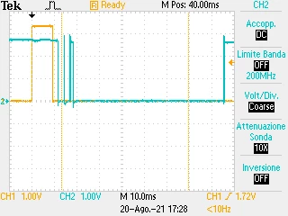
In order to investigate, I've used both outputs, the same software, just a set, and a reset after delay. I've connected the oscilloscope to see the output signal reported in the picture.

Tack yellow is the PB1 output (Trigger_pin), track blue is the PC2 output (Test_pin) the wrong one.
0693W00000DpxlKQAR.png 

My simple code.

uint16_t Distance(void) {
 
	uint16_t distanza = 0;
 
	UTIL_LPM_Mode_t lpm_stat = UTIL_LPM_GetMode();
//	UTIL_LPM_S
	APP_LOG(TS_OFF, VLEVEL_H, "\r\n###### ========== PASSO ==========, %d\r\n", lpm_stat);
	BSP_LED_On(LED_BLUE) ;
	HAL_GPIO_WritePin(Trigger_GPIO_Port, Trigger_Pin, GPIO_PIN_SET);
	#ifdef TEST_GPIO
	HAL_GPIO_WritePin(Test_GPIO_Port, Test_Pin, GPIO_PIN_SET);
	#endif
	HAL_Delay(10);
	BSP_LED_Off(LED_BLUE);
	HAL_GPIO_WritePin(Trigger_GPIO_Port, Trigger_Pin, GPIO_PIN_RESET);
	#ifdef TEST_GPIO
	HAL_GPIO_WritePin(Test_GPIO_Port, Test_Pin, GPIO_PIN_RESET);
	#endif
 

Now, PC2 doesn't seem used on the NUCLEO board it's free, so my question: I've done a mistake o there is some sort of bugs on the board?

F.

This topic has been closed for replies.
FRest.1
FRest.1Best answer
Associate III
Aug 23, 2021 9:39 AM UTC

I'm very sorry, I've wasted your time. I've made a mistake counting the PIN on the connector in reverse and wrong order so I was looking at the wrong pin.

What's worse is that I foolishly persevered.

My apologies and thank you for the help, it helped force me to revisit the connections.

F.

5 replies

FRest.1
FRest.1Author
Associate III
Aug 22, 2021 2:00 PM UTC

There is activity on PC2, but I'm not able to check what is controlling it.

F.

TDK
Aug 23, 2021 7:22 AM UTC

PC2 is not used per the user manual or the schematic. Recheck wiring, pin/port definitions. Gotta be an answer somewhere. Examine register values.

"If you feel a post has answered your question, please click ""Accept as Solution""."
Javier1
Principal
Aug 23, 2021 8:14 AM UTC

Maybe PC2 is declared as open drain? and what you see is the noise of the line being left floating?

hit me up in https://www.linkedin.com/in/javiermuñoz/
FRest.1
FRest.1AuthorBest answer
Associate III
Aug 23, 2021 9:39 AM UTC

I'm very sorry, I've wasted your time. I've made a mistake counting the PIN on the connector in reverse and wrong order so I was looking at the wrong pin.

What's worse is that I foolishly persevered.

My apologies and thank you for the help, it helped force me to revisit the connections.

F.

Javier1
Principal
Aug 24, 2021 7:26 AM UTC

happens to the best of us

hit me up in https://www.linkedin.com/in/javiermuñoz/