


Question
How start PWM duty cycle transfer throught DMA ?
I create a simple project with CUBE_MX in order to test DMA_PWM generation.
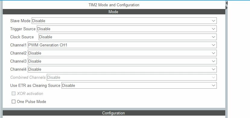
I configure the TIM2 like this :
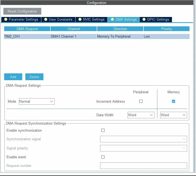
The DMA is configured this way:
in the main i fisrt enable the PWM channel(signal output is ok on scope) , then i try to start a DMA transfer to set the duty cycle to 10(buffer values) ..but when i check the duty cycle is still 40 (like it was at the timer initialisation)
So i think there is no transfer.
I'm quite new with DMA so i'm not sure my configuration is right...maybe i should not left DMA request synchronisation settings empty...?
Things i notice : DMA1_Channel1_IRQHandler seems never triggered...??
So what i am currently missing ?
Best regards,
Pierre
Here my code :
int main(void)
{
 /* USER CODE BEGIN 1 */

 /* USER CODE END 1 */

 /* MCU Configuration--------------------------------------------------------*/

 /* Reset of all peripherals, Initializes the Flash interface and the Systick. */
 HAL_Init();

 /* USER CODE BEGIN Init */

 /* USER CODE END Init */

 /* Configure the system clock */
 SystemClock_Config();

 /* USER CODE BEGIN SysInit */

 /* USER CODE END SysInit */

 /* Initialize all configured peripherals */
 MX_GPIO_Init();
 MX_DMA_Init();
 MX_TIM2_Init();
 /* USER CODE BEGIN 2 */

 uint32_t buffer[8] = {10,10,10,10,10,10,10,10 } ;

 if (HAL_TIM_PWM_Start(&htim2, TIM_CHANNEL_1) != HAL_OK)
 {
 /* PWM Generation Error */
 Error_Handler();
 }
 /* USER CODE END 2 */
 HAL_TIM_PWM_Start_DMA(&htim2, TIM_CHANNEL_1,buffer,sizeof(buffer));
 /* Infinite loop */
 /* USER CODE BEGIN WHILE */
 while (1)
 {
 /* USER CODE END WHILE */
	 HAL_GPIO_TogglePin(LED_GREEN_GPIO_Port,LED_GREEN_Pin);
	 HAL_Delay(1000);
 /* USER CODE BEGIN 3 */
 }
 /* USER CODE END 3 */
}

/**
 * @brief System Clock Configuration
 * @retval None
 */
void SystemClock_Config(void)
{
 RCC_OscInitTypeDef RCC_OscInitStruct = {0};
 RCC_ClkInitTypeDef RCC_ClkInitStruct = {0};
 RCC_PeriphCLKInitTypeDef PeriphClkInitStruct = {0};

 /** Configure the main internal regulator output voltage
 */
 __HAL_PWR_VOLTAGESCALING_CONFIG(PWR_REGULATOR_VOLTAGE_SCALE1);
 /** Initializes the RCC Oscillators according to the specified parameters
 * in the RCC_OscInitTypeDef structure.
 */
 RCC_OscInitStruct.OscillatorType = RCC_OSCILLATORTYPE_HSI|RCC_OSCILLATORTYPE_HSE;
 RCC_OscInitStruct.HSEState = RCC_HSE_ON;
 RCC_OscInitStruct.HSIState = RCC_HSI_ON;
 RCC_OscInitStruct.HSICalibrationValue = RCC_HSICALIBRATION_DEFAULT;
 RCC_OscInitStruct.PLL.PLLState = RCC_PLL_ON;
 RCC_OscInitStruct.PLL.PLLSource = RCC_PLLSOURCE_HSI;
 RCC_OscInitStruct.PLL.PLLM = RCC_PLLM_DIV1;
 RCC_OscInitStruct.PLL.PLLN = 8;
 RCC_OscInitStruct.PLL.PLLP = RCC_PLLP_DIV2;
 RCC_OscInitStruct.PLL.PLLR = RCC_PLLR_DIV2;
 RCC_OscInitStruct.PLL.PLLQ = RCC_PLLQ_DIV2;
 if (HAL_RCC_OscConfig(&RCC_OscInitStruct) != HAL_OK)
 {
 Error_Handler();
 }
 /** Configure the SYSCLKSource, HCLK, PCLK1 and PCLK2 clocks dividers
 */
 RCC_ClkInitStruct.ClockType = RCC_CLOCKTYPE_HCLK4|RCC_CLOCKTYPE_HCLK2
 |RCC_CLOCKTYPE_HCLK|RCC_CLOCKTYPE_SYSCLK
 |RCC_CLOCKTYPE_PCLK1|RCC_CLOCKTYPE_PCLK2;
 RCC_ClkInitStruct.SYSCLKSource = RCC_SYSCLKSOURCE_PLLCLK;
 RCC_ClkInitStruct.AHBCLKDivider = RCC_SYSCLK_DIV1;
 RCC_ClkInitStruct.APB1CLKDivider = RCC_HCLK_DIV1;
 RCC_ClkInitStruct.APB2CLKDivider = RCC_HCLK_DIV1;
 RCC_ClkInitStruct.AHBCLK2Divider = RCC_SYSCLK_DIV2;
 RCC_ClkInitStruct.AHBCLK4Divider = RCC_SYSCLK_DIV1;

 if (HAL_RCC_ClockConfig(&RCC_ClkInitStruct, FLASH_LATENCY_3) != HAL_OK)
 {
 Error_Handler();
 }
 /** Initializes the peripherals clocks
 */
 PeriphClkInitStruct.PeriphClockSelection = RCC_PERIPHCLK_SMPS;
 PeriphClkInitStruct.SmpsClockSelection = RCC_SMPSCLKSOURCE_HSI;
 PeriphClkInitStruct.SmpsDivSelection = RCC_SMPSCLKDIV_RANGE1;
 if (HAL_RCCEx_PeriphCLKConfig(&PeriphClkInitStruct) != HAL_OK)
 {
 Error_Handler();
 }
 /* USER CODE BEGIN Smps */

 /* USER CODE END Smps */
}

/**
 * @brief TIM2 Initialization Function
 * @param None
 * @retval None
 */
static void MX_TIM2_Init(void)
{

 /* USER CODE BEGIN TIM2_Init 0 */

 /* USER CODE END TIM2_Init 0 */

 TIM_MasterConfigTypeDef sMasterConfig = {0};
 TIM_OC_InitTypeDef sConfigOC = {0};

 /* USER CODE BEGIN TIM2_Init 1 */

 /* USER CODE END TIM2_Init 1 */
 htim2.Instance = TIM2;
 htim2.Init.Prescaler = 0;
 htim2.Init.CounterMode = TIM_COUNTERMODE_UP;
 htim2.Init.Period = 80;
 htim2.Init.ClockDivision = TIM_CLOCKDIVISION_DIV1;
 htim2.Init.AutoReloadPreload = TIM_AUTORELOAD_PRELOAD_ENABLE;
 if (HAL_TIM_PWM_Init(&htim2) != HAL_OK)
 {
 Error_Handler();
 }
 sMasterConfig.MasterOutputTrigger = TIM_TRGO_RESET;
 sMasterConfig.MasterSlaveMode = TIM_MASTERSLAVEMODE_DISABLE;
 if (HAL_TIMEx_MasterConfigSynchronization(&htim2, &sMasterConfig) != HAL_OK)
 {
 Error_Handler();
 }
 sConfigOC.OCMode = TIM_OCMODE_PWM1;
 sConfigOC.Pulse = 40;
 sConfigOC.OCPolarity = TIM_OCPOLARITY_HIGH;
 sConfigOC.OCFastMode = TIM_OCFAST_DISABLE;
 if (HAL_TIM_PWM_ConfigChannel(&htim2, &sConfigOC, TIM_CHANNEL_1) != HAL_OK)
 {
 Error_Handler();
 }
 __HAL_TIM_DISABLE_OCxPRELOAD(&htim2, TIM_CHANNEL_1);
 /* USER CODE BEGIN TIM2_Init 2 */

 /* USER CODE END TIM2_Init 2 */
 HAL_TIM_MspPostInit(&htim2);

}

/**
 * Enable DMA controller clock
 */
static void MX_DMA_Init(void)
{

 /* DMA controller clock enable */
 __HAL_RCC_DMAMUX1_CLK_ENABLE();
 __HAL_RCC_DMA1_CLK_ENABLE();

 /* DMA interrupt init */
 /* DMA1_Channel1_IRQn interrupt configuration */
 HAL_NVIC_SetPriority(DMA1_Channel1_IRQn, 0, 0);
 HAL_NVIC_EnableIRQ(DMA1_Channel1_IRQn);

}

/**
 * @brief GPIO Initialization Function
 * @param None
 * @retval None
 */
static void MX_GPIO_Init(void)
{
 GPIO_InitTypeDef GPIO_InitStruct = {0};

 /* GPIO Ports Clock Enable */
 __HAL_RCC_GPIOA_CLK_ENABLE();
 __HAL_RCC_GPIOB_CLK_ENABLE();

 /*Configure GPIO pin Output Level */
 HAL_GPIO_WritePin(LED_BLUE_GPIO_Port, LED_BLUE_Pin, GPIO_PIN_RESET);
 /*Configure GPIO pin Output Level */
 HAL_GPIO_WritePin(GPIOB, LED_GREEN_Pin|LED_RED_Pin, GPIO_PIN_RESET);

 /*Configure GPIO pin : LED_BLUE_Pin */
 GPIO_InitStruct.Pin = LED_BLUE_Pin;
 GPIO_InitStruct.Mode = GPIO_MODE_OUTPUT_PP;
 GPIO_InitStruct.Pull = GPIO_NOPULL;
 GPIO_InitStruct.Speed = GPIO_SPEED_FREQ_LOW;
 HAL_GPIO_Init(LED_BLUE_GPIO_Port, &GPIO_InitStruct);

 /*Configure GPIO pins : LED_GREEN_Pin LED_RED_Pin */
 GPIO_InitStruct.Pin = LED_GREEN_Pin|LED_RED_Pin;
 GPIO_InitStruct.Mode = GPIO_MODE_OUTPUT_PP;
 GPIO_InitStruct.Pull = GPIO_NOPULL;
 GPIO_InitStruct.Speed = GPIO_SPEED_FREQ_LOW;
 HAL_GPIO_Init(GPIOB, &GPIO_InitStruct);

}

/* USER CODE BEGIN 4 */

/* USER CODE END 4 */

/**
 * @brief This function is executed in case of error occurrence.
 * @retval None
 */
void Error_Handler(void)
{
 /* USER CODE BEGIN Error_Handler_Debug */
 /* User can add his own implementation to report the HAL error return state */

 /* USER CODE END Error_Handler_Debug */
}

#ifdef USE_FULL_ASSERT
/**
 * @brief Reports the name of the source file and the source line number
 * where the assert_param error has occurred.
 * @param file: pointer to the source file name
 * @param line: assert_param error line source number
 * @retval None
 */
void assert_failed(uint8_t *file, uint32_t line)
{
 /* USER CODE BEGIN 6 */
 /* User can add his own implementation to report the file name and line number,
 tex: printf("Wrong parameters value: file %s on line %d\r\n", file, line) */
 /* USER CODE END 6 */
}
#endif /* USE_FULL_ASSERT */

/************************ (C) COPYRIGHT STMicroelectronics *****END OF FILE****/