IKarg.1
Associate II
July 27, 2022
Question

current measurement (ADC) when pwm is ON.

  • July 27, 2022
  • 6 replies
  • 7451 views

Hi,

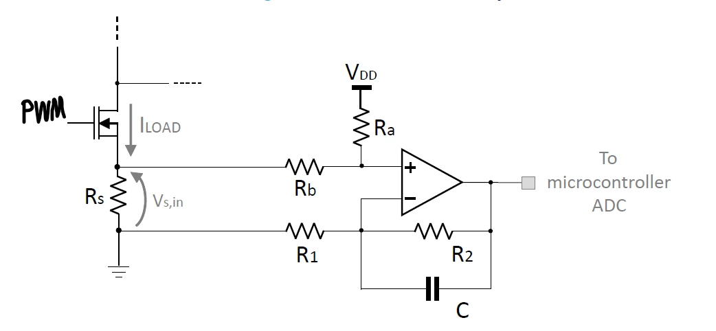
I have stm32wle5 and a circuit to measure current. stm32 will generate a PWM using timer1 ch1. The opamp's output is also connected to the ADC input of stm32. I want to measure the current (read ADC values) when PWM is on. Preferably in the middle of the PWM high edge. In most of the examples, people use internal triggers to trigger ADC. I thought as all channels of one timer have the same frequency, can I use one channel to output pwn and another channel as PWM generation without output just to trigger ADC? And set their duty_cycle and everything the same? I'm unsure if they are entirely synced and if this is the right solution. Do you have any other recommendations?

I also don't know how to do the measurement at the middle of PWM's high edge.

circuit:
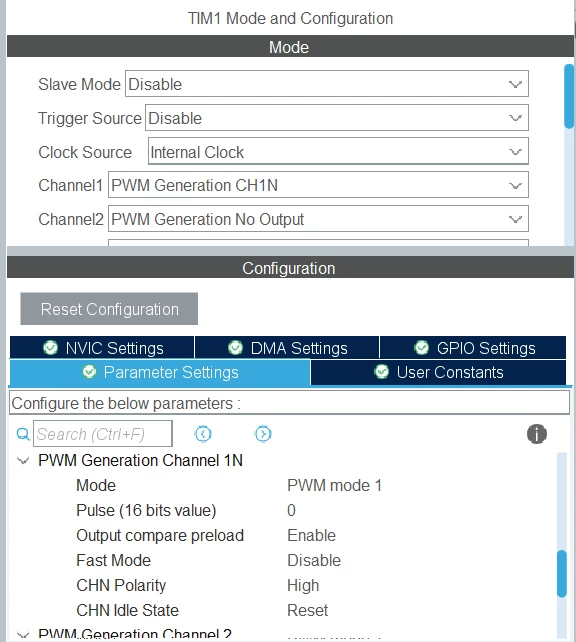
0693W00000QMHn8QAH.pngtimer1 and channel one config:

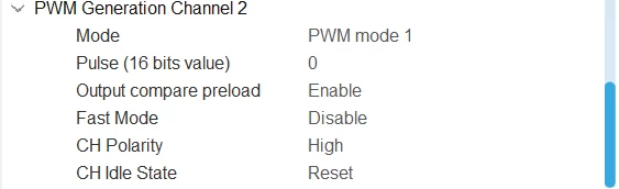
0693W00000QMHopQAH.pngtimer1 ch2 config:

0693W00000QMHp4QAH.png 

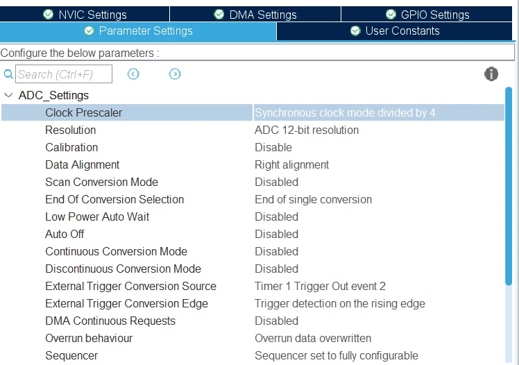
ADC config:

0693W00000QMHpiQAH.png 

Note that I don't do a continuous conversion and just want one or maybe a few samples and take the average in each PWM period.

Any help would be appreciated.

Thanks

UPDATE:

I want to do one single measurement every hour but do this when the MOSFET switch is on, e.g., PWM output is one.

This topic has been closed for replies.

6 replies

LMI2
Senior III
July 27, 2022

Isn't PWM quite slow. So you should be able know what is happening. Or take continuous readings and find out when the current starts to rise.

IKarg.1
IKarg.1Author
Associate II
July 28, 2022

I want to sense the current to find the change from the normal situation. And the PWM duty cycle will change in my code continuously. So, I think I cannot just measure the current all the time and figure out when it is rising. I cannot identify whether it is because of PWM's rising edge or the event I'm looking for.

I think this is a common current measurement circuit and should be a solution for it. Any one can help?

MasterT
Lead II
July 28, 2022

"

  1. I thought as all channels of one timer have the same frequency, can I use one channel to output pwn and another channel as PWM generation without output just to trigger ADC? 2.
  2. And set their duty_cycle and everything the same? I'm unsure if they are entirely synced and if this is the right solution. 3.
  3. Do you have any other recommendations?"

1 Same frequency.

2 No, duty cycle has to be 1/2 for channel - adc trigger. Depends on stm part number, some have "combine PWM" mode, some does not. TIM's w/o have all 4 channels in sync, adjusting duty cycle you can only change timing of the falling edge, so configure ADC trigger accordingly.

I 'd configure 2 channel in PWM-output mode and observe two signal on dual channel oscilloscope, than varying phase one of the PWM observe ADC readings.

3 This is the best solution, read more in ST app note AN4449

IKarg.1
IKarg.1Author
Associate II
July 28, 2022

Thanks. I'll try this.

IKarg.1
IKarg.1Author
Associate II
August 3, 2022

I tested this but don't get stable values, especially in high frequencies. I added an "update" section to my question. Does this change anything? I want to measure the current every hour, but when PWM is 1.

Can I just check if the PWM value is one and then do the measurement? Not sure about the delays here if something like an if statement can be a solution.

MasterT
Lead II
August 3, 2022

Better to measure each PWM cycle, transfer data to memory using DMA. Than when 1-4k Bytes buffer is full, you can run averaging algorithm to reduce noise. 1k data could provide 5 additional bits accuracy to the result value.

I have no experience with stm32wl product line, but there are examples in CubeMX, check it out:

https://github.com/STMicroelectronics/STM32CubeWL/tree/main/Projects/NUCLEO-WL55JC/Examples/ADC