BL072Z LoRa node high current consumption in low power mode
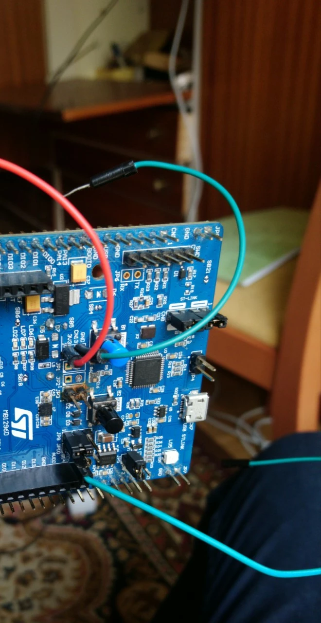
Hi, I am making some test in low power mode using the end_node example for LoRa but I always get 0.5mA in sleep mode, I use the STM32CubeExpansion_LRWAN_V1.2.1 version and I am doing measurements in the JP3 VDD_MCU_LRA branch
I have read this post where @Remco Groenendaal recommend us this:
To get to the lowest power consumption mode using the B072, one should:
1.- be absolutely sure TCXO is not connected to vdd but connected to PA12 (vdd_tcxo)
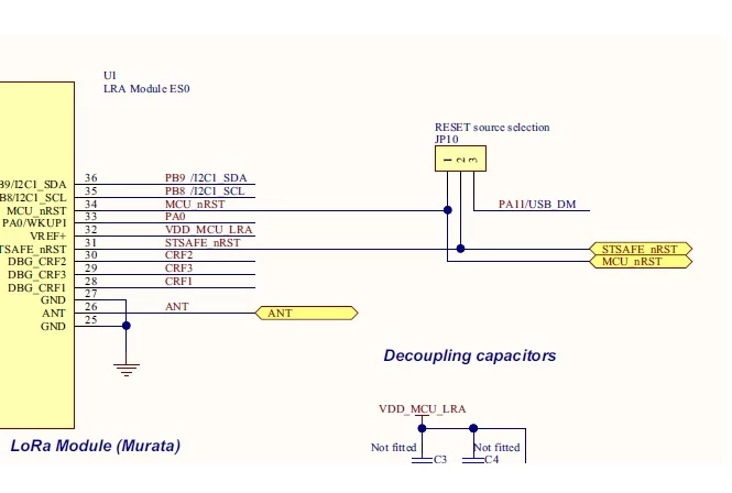
I have changed JP9 to pins 1-2 but is the same
and in the same post @Kevin Genskowsky told us this:
Finaly solve it ,
Conected VDD_TCX0 to PA10
and changed ,mlm32l0xx_hw_conf.h
♯ define RADIO_TCXO_VCC_PORT GPIOA
,
♯ define RADIO_TCXO_VCC_PIN GPIO_PIN_10
And worked imidiatly PA12 might have some extra configuration that is missing.
So this is very confuse because I don't know if is necessary to change the control pin of TCXO or the solution is just change the position of JP9, or both
2.- set all your defined (and unused) pins to analog before entering lowpower mode, and restore them after resuming from low power
3.- deinit all the perhiperals before entering lowpower, and init them again them upon resuming
inside the low power function points 2 and 3 are already done:
//********************inside LPM_EnterStopMode();

static void HW_IoDeInit( void )
{
 /* HW_SPI_IoDeInit( );*/
 GPIO_InitTypeDef initStruct={0};

 initStruct.Mode =GPIO_MODE_ANALOG;
 initStruct.Pull =GPIO_NOPULL;
 HW_GPIO_Init ( RADIO_MOSI_PORT, RADIO_MOSI_PIN, &initStruct );
 HW_GPIO_Init ( RADIO_MISO_PORT, RADIO_MISO_PIN, &initStruct );
 HW_GPIO_Init ( RADIO_SCLK_PORT, RADIO_SCLK_PIN, &initStruct );
 HW_GPIO_Init ( RADIO_NSS_PORT, RADIO_NSS_PIN , &initStruct );

 Radio.IoDeInit( );

 vcom_IoDeInit( );
}

void vcom_IoDeInit(void)
{
 GPIO_InitTypeDef GPIO_InitStructure={0};

 USARTx_TX_GPIO_CLK_ENABLE();

 GPIO_InitStructure.Mode = GPIO_MODE_ANALOG;
 GPIO_InitStructure.Pull = GPIO_NOPULL;

 GPIO_InitStructure.Pin = USARTx_TX_PIN ;
 HAL_GPIO_Init( USARTx_TX_GPIO_PORT, &GPIO_InitStructure );

 GPIO_InitStructure.Pin = USARTx_RX_PIN ;
 HAL_GPIO_Init( USARTx_RX_GPIO_PORT, &GPIO_InitStructure );
}

//******************inside LPM_ExitStopMode();
void LPM_ExitStopMode( void)
{
 /* Disable IRQ while the MCU is not running on HSI */

 BACKUP_PRIMASK();

 DISABLE_IRQ( );

 /* After wake-up from STOP reconfigure the system clock */
 /* Enable HSI */
 __HAL_RCC_HSI_ENABLE();

 /* Wait till HSI is ready */
 while( __HAL_RCC_GET_FLAG(RCC_FLAG_HSIRDY) == RESET ) {}

 /* Enable PLL */
 __HAL_RCC_PLL_ENABLE();
 /* Wait till PLL is ready */
 while( __HAL_RCC_GET_FLAG( RCC_FLAG_PLLRDY ) == RESET ) {}

 /* Select PLL as system clock source */
 __HAL_RCC_SYSCLK_CONFIG ( RCC_SYSCLKSOURCE_PLLCLK );

 /* Wait till PLL is used as system clock source */
 while( __HAL_RCC_GET_SYSCLK_SOURCE( ) != RCC_SYSCLKSOURCE_STATUS_PLLCLK ) {}

 /*initilizes the peripherals*/
 HW_IoInit( );

 RESTORE_PRIMASK( );
}
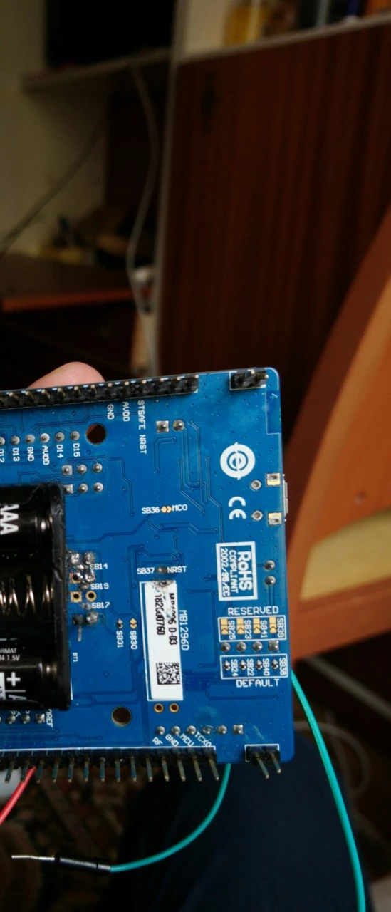
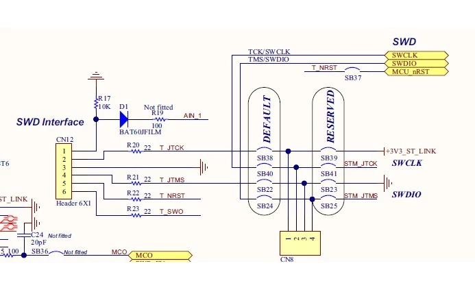
4.- float the board e.g.: disconnect any st-link or other debuggers, also the onboard usb segger j-link
are you talking about remove CN8? I don't understand this
5.- run it from batteries and disconnect serial debug when doing the current measurements
a.- debug,trace and sensors are disabled
b.- why is necessary to run from batteries? I mean, the consumption should be the same if you power the board from batteries or USB (or not?) and also, if you remove the solder bridge (SB37) to enable the power from batteries you can not load your code anymore because ST-LINK is disconnected
If anyone has an idea how to resolve this problem please share it, I also read that someone got lower currents using a previous version of the end_node example so it seems this is a common problem
I will continue doing tests and will share you any advance, thanks