


LCD HD44780 interface problems with Nucleo board
Hello all members,
I am interfacing LCD module in 8bit mode to STM32F446RE Nucleo board the connections are as below:
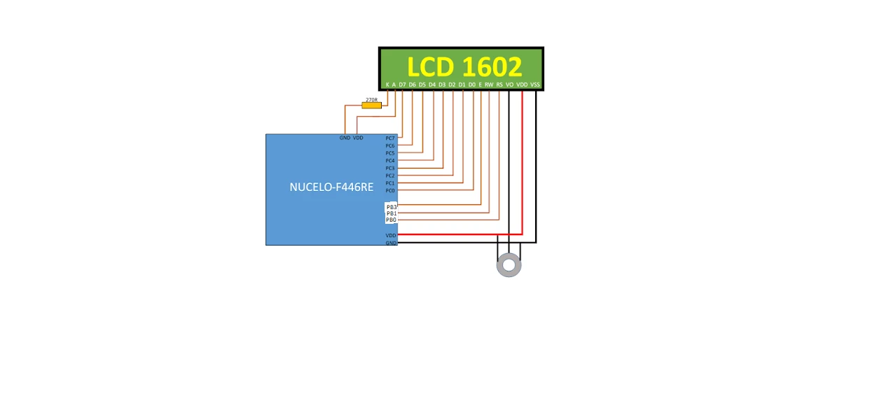 The pin connections(if unclear in diagram):
Control pins:
RS-->PB0
RW-->PB1
E-->PB3
8bit data pins LCD:
D0-D7-->PC0-PC7
Program Lcd.c:
 #include "lcd.h"

 #include <stdint.h>

 #include "delay.h"


 GPIO_Handle_t GPIOConfig;

 void lcd_init()

 {


 	/*

 	 *

 	 * Step1: Make Control pins and LCD 8pins as o/p

 	 * Step2: Initialising sequence as per datasheet

 	 */

 //Each of this function enable's clock and configures the pin to o/p mode

 	LCDControlpins_init(GPIO_PIN_NO_0);

 	LCDControlpins_init(GPIO_PIN_NO_1);

 	LCDControlpins_init(GPIO_PIN_NO_3);

 //Each of this function enable's clock and configures the pin to o/p mode for PC0-PC7 pins

 	for(int x=0;x<=7;x++)

 		LCDDatapins_init(x);


 	/*

 	 * Init sequence:

 	 * as per datasheet

 	 *

 	 */

 	delay_ms(100); // all delays are 3/more times the delay specified in

 datasheet

 	send_cmd(0x30);

 	delay_ms(7);

 	send_cmd(0x30);

 	delay_ms(7);

 	send_cmd(0x30);

 	delay_ms(7);


 	send_cmd(0x38);		// Sets no of lines= 2 and F font = 8*5 pixel type

 	delay_ms(7);


 	send_cmd(0x08);		//Sets D,C,B off (Display Cursor,Blink)

 	delay_ms(7);


 	send_cmd(0x01);		//clears the entire display

 	delay_ms(7);


 	send_cmd(0x07);	 //I/D=1,S=1 sets the increment of cursor from left to right and no shift

 of the data.

 	delay_ms(7);


 }


 void LCDControlpins_init(uint8_t pinno)

 {

 	GPIOConfig.pGPIOx=GPIOB;

 	GPIOConfig.GPIO_PinConfig.GPIO_PinMode=GPIO_MODE_OUT;

 	GPIOConfig.GPIO_PinConfig.GPIO_PinOPType=GPIO_OP_TYPE_PP;

 	GPIOConfig.GPIO_PinConfig.GPIO_PinSpeed=GPIO_SPEED_LOW;


 	switch(pinno)

 	{

 		case 0:

 			GPIOConfig.GPIO_PinConfig.GPIO_PinNumber=GPIO_PIN_NO_0;

 			break;

 		case 1:

 			GPIOConfig.GPIO_PinConfig.GPIO_PinNumber=GPIO_PIN_NO_1;

 			break;

 		case 3:

 			GPIOConfig.GPIO_PinConfig.GPIO_PinNumber=GPIO_PIN_NO_3;

 			break;

 		default :

 			break;

 	}

 	GPIO_Init(&GPIOConfig);

 }


 void LCDDatapins_init(uint8_t pinno)

 {

 	GPIOConfig.pGPIOx=GPIOC;

 	GPIOConfig.GPIO_PinConfig.GPIO_PinMode=GPIO_MODE_OUT;

 	GPIOConfig.GPIO_PinConfig.GPIO_PinOPType=GPIO_OP_TYPE_PP;

 	GPIOConfig.GPIO_PinConfig.GPIO_PinSpeed=GPIO_SPEED_LOW;

 	GPIOConfig.GPIO_PinConfig.GPIO_PinNumber=pinno;

 	GPIO_Init(&GPIOConfig);

 }


 void send_cmd(unsigned char cmd)

 {

 	/*

 	 * RS=0,RW=0,EN=0

 	 */

 	GPIO_WriteToOutputPin(GPIOB, GPIO_PIN_NO_0, 0); //RS as Instruction

 	GPIO_WriteToOutputPin(GPIOB, GPIO_PIN_NO_1, 0); //RW

 	GPIO_WriteToOutputPin(GPIOB, GPIO_PIN_NO_3, 0); //E

 	delay_ms(5); //extra setup time

 	GPIO_WriteToOutputPort(GPIOC,(uint16_t)cmd);

 	delay_ms(5); //extra setup time

 //Make E pin High to Low with reasonable wait time (more than time specified in datasheet)

 	GPIO_WriteToOutputPin(GPIOB, GPIO_PIN_NO_3, 1); //E=high

 	delay_ms(2);

 	GPIO_WriteToOutputPin(GPIOB, GPIO_PIN_NO_3, 0); //E=low

 	delay_ms(2);


 }


 void send_data(unsigned char data)

 {

 	/*

 	 * Step1: Set function set 0x38 value

 	 * Step2: Set 0x0e value that is display and cursor on no blink

 	 * Step3: Set 0x06 that is increment by 1 and shift display

 	 * Step4: write data

 	 */

 	send_cmd(0x38);delay_ms(7);

 	send_cmd(0x0E);delay_ms(7);

 	send_cmd(0x06);delay_ms(7);

 	GPIO_WriteToOutputPin(GPIOB, GPIO_PIN_NO_0, 1); //RS as data

 	GPIO_WriteToOutputPin(GPIOB, GPIO_PIN_NO_1, 0); //RW as write

 	GPIO_WriteToOutputPin(GPIOB, GPIO_PIN_NO_3, 0); //E

 	delay_ms(5); //extra setup time

 	GPIO_WriteToOutputPort(GPIOC,(uint16_t)data);

 	delay_ms(5); //extra setup time

 	GPIO_WriteToOutputPin(GPIOB, GPIO_PIN_NO_3, 1); //E=high

 	delay_ms(2);

 	GPIO_WriteToOutputPin(GPIOB, GPIO_PIN_NO_3, 0); //E=low

 	delay_ms(2);


 }
Program lcd.h
#ifndef LCD_H_

 #define LCD_H_

 #include <stdint.h>

 #include "STM32fxx_gpio.h"

 void LCDControlpins_init(uint8_t);

 void LCDDatapins_init(uint8_t );

 void send_cmd(unsigned char );

 void send_data(unsigned char );

 void lcd_init(void);

 #define RS	0

 #define RW	1

 #define E	3


 #endif /* LCD_H_ */
The code for delay.c file using SYSTICK & polling method:
 #include "delay.h"

 typedef struct

 		{

 			uint32_t CSR;

 			uint32_t RVR;

 			uint32_t CVR;

 			uint32_t CALIB;

 		}SYST_t;


 SYST_t *SYSTick = (SYST_t*)0xE000E010;


 //Initialise systick timer

 void systickinit()

 {

 	SYSTick->CSR|=(1<<2); //take processor as clock source for timer

 }


 //delay function for 1us delay

 void delay_us(uint32_t blinktime)

 {


 	systickinit();

 	for(int i=0;i<blinktime;i++)

 	{

 	SYSTick->RVR = 16; //reload value for 1us

 	SYSTick->CSR|=(1<<0);//enable the timer countdown

 	while(!(SYSTick->CSR & (1<<16) )); //count down flag until set

 	//SYSTick->CSR &=~(1<<16); //reset the countdown flag

 	SYSTick->CSR&=~(1<<0); //disable the timer


 	}

 }


 void delay_ms(uint32_t blinktime)

 {

 		blinktime*=1000;

 			delay_us(blinktime);

 }


 void delay(uint32_t count)			//provides for loopdelyin ms

 {

 		int i,j;

 		count=count*1000;

 		for(i=0;i<count;i++)

 		for(j=0;j<16;j++);		//gives 1us delay

 }
delay.h file:
 #ifndef DELAY_H_

 #define DELAY_H_

 #include <stdint.h>


 void delay_us(uint32_t blinktime);

 void delay_ms(uint32_t blinktime);

 void delay(uint32_t count);

 void systickinit(void);

 typedef struct

 {

 	uint32_t CSR;

 	uint32_t RVR;

 	uint32_t CVR;

 	uint32_t CALIB;

 }SYST;


 #endif /* DELAY_H_ */
The main.c:
 #include "STM32fxx_gpio.h"

 #include "lcd.h"

 int main(void)

 {

 	lcd_init();

 	send_data('H');

 	send_data('E');

 	for(;;);

 }
The header file for gpio API's are in below github links:
Header file for STM peripheral specific registers
Header for GPIO file and GPIO functions .c files for GPIO clock and pin /port config functions:
Dear members,
I have pasted all my codes.. The GPIO.h,.c files are 100percent working fine I have checked with other peripheral projects. The delay function also works correctly tested for led blink...
Now I am stuck in LCD program only..
My main aim is to just display 1 character I have gone through datasheet and forums and have taken everyones's suggestion accurately I still can't figure out what's wrong with my program..
I have tried this LCD board for arduino program it works there.
Also I have checked voltage specifications and all pin's connected are 5v Tolerant as per stm32 datasheet.
Please can someone figure out whta I may be doing wrong..
Your suggestions may help me..
I would be greateful..