

Solved
How to translate ILI9341 driver in touchgfx project to HAL version?
TFT-LCD driver:
void touchgfxDisplayDriverTransmitBlock(const uint8_t* pixels, uint16_t x, uint16_t y, uint16_t w, uint16_t h)
{
 static uint16_t old_x0=0xFFFF, old_x1=0xFFFF, old_y0=0xFFFF, old_y1=0xFFFF;
 IsTransmittingBlock_ = 1;

 uint16_t x1 = x + w - 1;
 uint16_t y1 = y + h - 1;

 // Set columns, if changed
 if (x != old_x0 || x1 != old_x1)
 {
 parameter[0] = (x >> 8) & 0xFF;
 parameter[1] = x & 0xFF;
 parameter[2] = (x1 >> 8) & 0xFF;
 parameter[3] = x1 & 0xFF;
 send_cmd(DCS_SET_COLUMN_ADDRESS, parameter, 4);

 old_x0 = x;
 old_x1 = x1;
 }

 // Set rows, if changed
 if (y != old_y0 || y1 != old_y1)
 {
 parameter[0] = (y >> 8) & 0xFF;
 parameter[1] = y & 0xFF;
 parameter[2] = (y1 >> 8) & 0xFF;
 parameter[3] = y1 & 0xFF;
 send_cmd(DCS_SET_PAGE_ADDRESS, parameter, 4);

 old_y0 = y;
 old_y1 = y1;
 }

 send_cmd(DCS_WRITE_MEMORY_START, NULL, 0);
 send_data((uint16_t*)pixels, w * h);
}

int touchgfxDisplayDriverTransmitActive(void)
{
 return IsTransmittingBlock_;
}

void HAL_GPIO_EXTI_Rising_Callback(uint16_t GPIO_Pin)
{
 if (GPIO_Pin == DISP_TE_Pin)
 {
 tearingEffectCount++;
 touchgfxSignalVSync();
 }
}

static void send_cmd(uint8_t cmd, uint8_t * parameter, uint16_t size)
{
 HAL_GPIO_WritePin(DISP_CS_GPIO_Port, DISP_CS_Pin, GPIO_PIN_RESET);
 HAL_GPIO_WritePin(DISP_DCX_GPIO_Port, DISP_DCX_Pin, GPIO_PIN_RESET);
 HAL_SPI_Transmit(&hspi1, &cmd, 1, HAL_MAX_DELAY);

 if (parameter != NULL && size > 0)
 {
 HAL_GPIO_WritePin(DISP_DCX_GPIO_Port, DISP_DCX_Pin, GPIO_PIN_SET);
 HAL_SPI_Transmit(&hspi1, parameter, size, HAL_MAX_DELAY);
 }

 HAL_GPIO_WritePin(DISP_CS_GPIO_Port, DISP_CS_Pin, GPIO_PIN_SET);
}

static void send_data(uint16_t * data, uint16_t size)
{
 hspi1.Init.DataSize = SPI_DATASIZE_16BIT;
 if (HAL_SPI_Init(&hspi1) != HAL_OK)
 {
 Error_Handler();
 }

 HAL_GPIO_WritePin(DISP_CS_GPIO_Port, DISP_CS_Pin, GPIO_PIN_RESET);
 HAL_GPIO_WritePin(DISP_DCX_GPIO_Port, DISP_DCX_Pin, GPIO_PIN_SET);
 HAL_SPI_Transmit_DMA(&hspi1, (const uint8_t *)data, size);
}
void HAL_SPI_TxCpltCallback(SPI_HandleTypeDef *hspi)
{
 if (hspi == &hspi1)
 {
 IsTransmittingBlock_ = 0;
 HAL_GPIO_WritePin(DISP_CS_GPIO_Port, DISP_CS_Pin, GPIO_PIN_SET);

 hspi1.Init.DataSize = SPI_DATASIZE_8BIT;
 if (HAL_SPI_Init(&hspi1) != HAL_OK)
 {
 Error_Handler();
 }

 DisplayDriver_TransferCompleteCallback();
 }
}
SPI-FLASH driver:
extern SPI_HandleTypeDef hspi2;

volatile uint8_t isReceivingData = 0;

void DataReader_WaitForReceiveDone(void)
{
 while(isReceivingData)
 {}
}

void DataReader_ReadData(uint32_t address24, uint8_t* buffer, uint32_t length)
{
 uint8_t cmd[4];
 cmd[0] = CMD_READ;
 cmd[1] = (address24 >> 16) & 0xFF;
 cmd[2] = (address24 >> 8) & 0xFF;
 cmd[3] = address24 & 0xFF;

 HAL_GPIO_WritePin(FLASH_CS_GPIO_Port, FLASH_CS_Pin, GPIO_PIN_RESET);
 HAL_SPI_Transmit(&hspi2, cmd, 4, HAL_MAX_DELAY);
 HAL_SPI_Receive(&hspi2, buffer, length, HAL_MAX_DELAY);
 HAL_GPIO_WritePin(FLASH_CS_GPIO_Port, FLASH_CS_Pin, GPIO_PIN_SET);
}

void DataReader_StartDMAReadData(uint32_t address24, uint8_t* buffer, uint32_t length)
{
 uint8_t cmd[4];
 cmd[0] = CMD_READ;
 cmd[1] = (address24 >> 16) & 0xFF;
 cmd[2] = (address24 >> 8) & 0xFF;
 cmd[3] = address24 & 0xFF;

 HAL_GPIO_WritePin(FLASH_CS_GPIO_Port, FLASH_CS_Pin, GPIO_PIN_RESET);
 HAL_SPI_Transmit(&hspi2, cmd, 4, HAL_MAX_DELAY);
 HAL_SPI_Receive_DMA(&hspi2, buffer, length);
}

void HAL_SPI_RxCpltCallback(SPI_HandleTypeDef *hspi)
{
 if (hspi == &hspi2)
 {
 isReceivingData = 0;
 HAL_GPIO_WritePin(FLASH_CS_GPIO_Port, FLASH_CS_Pin, GPIO_PIN_SET);
 }
}
I code as above,but the screen displays black line:
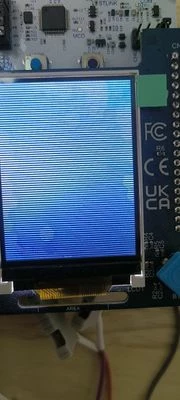
I'm not sure whether my
static void send_data(uint16_t * data, uint16_t size)
{
 hspi1.Init.DataSize = SPI_DATASIZE_16BIT;
 if (HAL_SPI_Init(&hspi1) != HAL_OK)
 {
 Error_Handler();
 }

 HAL_GPIO_WritePin(DISP_CS_GPIO_Port, DISP_CS_Pin, GPIO_PIN_RESET);
 HAL_GPIO_WritePin(DISP_DCX_GPIO_Port, DISP_DCX_Pin, GPIO_PIN_SET);
 HAL_SPI_Transmit_DMA(&hspi1, (const uint8_t *)data, size);
}
void HAL_SPI_TxCpltCallback(SPI_HandleTypeDef *hspi)
{
 if (hspi == &hspi1)
 {
 IsTransmittingBlock_ = 0;
 HAL_GPIO_WritePin(DISP_CS_GPIO_Port, DISP_CS_Pin, GPIO_PIN_SET);

 hspi1.Init.DataSize = SPI_DATASIZE_8BIT;
 if (HAL_SPI_Init(&hspi1) != HAL_OK)
 {
 Error_Handler();
 }

 DisplayDriver_TransferCompleteCallback();
 }
}
and
void DataReader_StartDMAReadData(uint32_t address24, uint8_t* buffer, uint32_t length)
{
 uint8_t cmd[4];
 cmd[0] = CMD_READ;
 cmd[1] = (address24 >> 16) & 0xFF;
 cmd[2] = (address24 >> 8) & 0xFF;
 cmd[3] = address24 & 0xFF;

 HAL_GPIO_WritePin(FLASH_CS_GPIO_Port, FLASH_CS_Pin, GPIO_PIN_RESET);
 HAL_SPI_Transmit(&hspi2, cmd, 4, HAL_MAX_DELAY);
 HAL_SPI_Receive_DMA(&hspi2, buffer, length);
}

void HAL_SPI_RxCpltCallback(SPI_HandleTypeDef *hspi)
{
 if (hspi == &hspi2)
 {
 isReceivingData = 0;
 HAL_GPIO_WritePin(FLASH_CS_GPIO_Port, FLASH_CS_Pin, GPIO_PIN_SET);
 }
}
are correct or not.
My board: NUCLEO-U083RC + X-NUCLEO-GFX01M2
/**********************************************************************************************************************************/
Official TFT-LCD driver:
#include "stm32u0xx_hal.h"
#include "DCS.h"
#include "main.h"
#include "MB1642DisplayDriver.h"
#include <assert.h>

extern SPI_HandleTypeDef hspi1;
extern DMA_HandleTypeDef hdma_spi1_tx;
extern TIM_HandleTypeDef htim6;

volatile uint16_t tearingEffectCount = 0;

//Signal TE interrupt to TouchGFX
void touchgfxSignalVSync(void);
void setVSYNC(void);
void clearVSYNC(void);

static void Display_DCS_Send(uint8_t command)
{
 // Reset the nCS pin
 DISPLAY_CSX_GPIO_Port->BRR = DISPLAY_CSX_Pin;
 // Set the DCX pin
 DISPLAY_DCX_GPIO_Port->BRR = DISPLAY_DCX_Pin;

 // Send the command
 *((__IO uint8_t*)&hspi1.Instance->DR) = command;

 // Wait until the bus is not busy before changing configuration
 while(((hspi1.Instance->SR) & SPI_FLAG_BSY) != RESET)
 {}

 // Reset the DCX pin
 DISPLAY_DCX_GPIO_Port->BSRR = DISPLAY_DCX_Pin;

 // Set the nCS
 DISPLAY_CSX_GPIO_Port->BSRR = DISPLAY_CSX_Pin;
}

static uint8_t Display_DCS_Read(uint8_t address)
{
 // Set the clock prescaler to a high number to avoid reading to fast from the display
 const uint32_t originalPrescaler = *((__IO uint32_t*)&hspi1.Instance->CR1) & SPI_CR1_BR_Msk;
 *((__IO uint32_t*)&hspi1.Instance->CR1) &= ~SPI_CR1_BR_Msk;
 *((__IO uint32_t*)&hspi1.Instance->CR1) |= SPI_CR1_BR_Msk & SPI_BAUDRATEPRESCALER_256;

 // Reset the nCS pin
 DISPLAY_CSX_GPIO_Port->BRR = DISPLAY_CSX_Pin;

 // Reset the DCX pin
 DISPLAY_DCX_GPIO_Port->BRR = DISPLAY_DCX_Pin;

 // Send the command
 *((__IO uint8_t*)&hspi1.Instance->DR) = address;
 while(((hspi1.Instance->SR) & SPI_FLAG_BSY))
 {}

 // Set the DCX pin
 DISPLAY_DCX_GPIO_Port->BSRR = DISPLAY_DCX_Pin;

 // Empty the RX buffer
 while (hspi1.Instance->SR & SPI_FLAG_RXNE)
 {
	 *((__IO uint8_t*)&hspi1.Instance->DR);
 }

 // Receive the data
 *((__IO uint8_t*)&hspi1.Instance->DR) = 0;
 while(((hspi1.Instance->SR) & SPI_FLAG_BSY))
 {}
 uint8_t data = *((__IO uint8_t*)&hspi1.Instance->DR);

 // Set the nCS
 DISPLAY_CSX_GPIO_Port->BSRR = DISPLAY_CSX_Pin;

 // Set the clock prescaler to the original value
 *((__IO uint32_t*)&hspi1.Instance->CR1) &= ~SPI_CR1_BR_Msk;
 *((__IO uint32_t*)&hspi1.Instance->CR1) |= originalPrescaler;

 return data;
}

static void Display_DCS_Send_With_Data(uint8_t command, uint8_t* data, uint8_t size)
{
 // Reset the nCS pin
 DISPLAY_CSX_GPIO_Port->BRR = DISPLAY_CSX_Pin;
 // Set the DCX pin
 DISPLAY_DCX_GPIO_Port->BRR = DISPLAY_DCX_Pin;

 *((__IO uint8_t*)&hspi1.Instance->DR) = command;

 // Wait until the bus is not busy before changing configuration
 while(((hspi1.Instance->SR) & SPI_FLAG_BSY) != RESET)
 {}
 DISPLAY_DCX_GPIO_Port->BSRR = DISPLAY_DCX_Pin;

 while (size > 0U)
 {
 *((__IO uint8_t*)&hspi1.Instance->DR) = *data;
 data++;
 size--;
 /* Wait until TXE flag is set to send data */
 while(((hspi1.Instance->SR) & SPI_FLAG_TXE) != SPI_FLAG_TXE)
 {}
 }

 // Wait until the bus is not busy before changing configuration
 while(((hspi1.Instance->SR) & SPI_FLAG_BSY) != RESET)
 {}

 // Set the nCS
 DISPLAY_CSX_GPIO_Port->BSRR = DISPLAY_CSX_Pin;
}

void DisplayDriver_DisplayOn(void)
{
 // Display ON
 Display_DCS_Send(DCS_SET_DISPLAY_ON);
 HAL_Delay(100);
}

void Display_OFF(void)
{
 // Display OFF
 Display_DCS_Send(DCS_SET_DISPLAY_OFF);
 HAL_Delay(100);
}

static uint16_t old_x0=0xFFFF, old_x1=0xFFFF, old_y0=0xFFFF, old_y1=0xFFFF;

void Display_Set_Area(uint16_t x0, uint16_t y0,
 uint16_t x1, uint16_t y1)
{
 uint8_t arguments[4];

 // Set columns, if changed
 if (x0 != old_x0 || x1 != old_x1)
 {
 arguments[0] = x0 >> 8;
 arguments[1] = x0 & 0xFF;
 arguments[2] = x1 >> 8;
 arguments[3] = x1 & 0xFF;
 Display_DCS_Send_With_Data(0x2A, arguments, 4);

 old_x0 = x0;
 old_x1 = x1;
 }

 // Set rows, if changed
 if (y0 != old_y0 || y1 != old_y1)
 {
 arguments[0] = y0 >> 8;
 arguments[1] = y0 & 0xFF;
 arguments[2] = y1 >> 8;
 arguments[3] = y1 & 0xFF;
 Display_DCS_Send_With_Data(0x2B, arguments, 4);

 old_y0 = y0;
 old_y1 = y1;
 }
}

volatile uint8_t IsTransmittingBlock_;
void Display_Bitmap(const uint16_t *bitmap, uint16_t posx, uint16_t posy, uint16_t sizex, uint16_t sizey)
{
 IsTransmittingBlock_ = 1;
 __HAL_SPI_ENABLE(&hspi1); // Enables SPI peripheral
 uint8_t command = DCS_WRITE_MEMORY_START;

 // Define the display area
 Display_Set_Area(posx, posy, posx+sizex-1, posy+sizey-1);

 // Reset the nCS pin
 DISPLAY_CSX_GPIO_Port->BRR = DISPLAY_CSX_Pin;
 // Set the DCX pin
 DISPLAY_DCX_GPIO_Port->BRR = DISPLAY_DCX_Pin;

 *((__IO uint8_t*)&hspi1.Instance->DR) = command;

 // Wait until the bus is not busy before changing configuration
 while(((hspi1.Instance->SR) & SPI_FLAG_BSY) != RESET)
 {}
 DISPLAY_DCX_GPIO_Port->BSRR = DISPLAY_DCX_Pin;

 // Set the SPI in 16-bit mode to match endianess
 hspi1.Instance->CR2 = SPI_DATASIZE_16BIT;

 // Disable spi peripherals
 __HAL_SPI_DISABLE(&hspi1);
 __HAL_DMA_DISABLE(&hdma_spi1_tx);

 CLEAR_BIT(hspi1.Instance->CR2, SPI_CR2_LDMATX);

 /* Clear all flags */
 __HAL_DMA_CLEAR_FLAG(&hdma_spi1_tx, (DMA_FLAG_GI1 << (hdma_spi1_tx.ChannelIndex & 0x1cU)));

 /* Configure DMA Channel data length */
 hdma_spi1_tx.Instance->CNDTR = sizex*sizey;
 /* Configure DMA Channel destination address */
 hdma_spi1_tx.Instance->CPAR = (uint32_t)&hspi1.Instance->DR;

 /* Configure DMA Channel source address */
 hdma_spi1_tx.Instance->CMAR = (uint32_t)bitmap;

 /* Disable the transfer half complete interrupt */
 __HAL_DMA_DISABLE_IT(&hdma_spi1_tx, DMA_IT_HT);
 /* Enable the transfer complete interrupt */
 __HAL_DMA_ENABLE_IT(&hdma_spi1_tx, (DMA_IT_TC | DMA_IT_TE));

 /* Enable the Peripherals */
 __HAL_DMA_ENABLE(&hdma_spi1_tx);
 __HAL_SPI_ENABLE(&hspi1);

 /* Enable Tx DMA Request */
 SET_BIT(hspi1.Instance->CR2, SPI_CR2_TXDMAEN);
}

void HAL_GPIO_EXTI_Rising_Callback(uint16_t GPIO_Pin)
{
 UNUSED(GPIO_Pin);

 if (GPIO_Pin == DISPLAY_TEARING_EFFECT_Pin)
 {
 // The draw speed of displays varies based on factors such as design, production variance, temperature and so on
 // to achieve good performance on all displays the timer tick rate needs to be adjusted based on the actual draw time of the latest frame
 // The following code dynamically adjusts the prescaler on every new frame to match the draw rate
 const uint32_t TARGET = DCS_DISPLAY_HEIGHT; // Number of lines in display drawing direction
 volatile uint32_t count = __HAL_TIM_GET_COUNTER(&htim6);
 if(count < TARGET - 1 || count > TARGET + 1)
 {
 const uint16_t oldPrescaler = htim6.Instance->PSC;
 const uint16_t newPrescaler = (count * oldPrescaler + TARGET / 2) / TARGET;

 // Check if the proposed new prescaler is in a reasonable range
 if (newPrescaler > 1000 && newPrescaler < 5000)
 {
 htim6.Instance->PSC = newPrescaler;
 htim6.Instance->EGR = TIM_EGR_UG; // Reinitialize the counter and generates an update of the registers
 }
 }
 (&htim6)->Instance->CR1 &= ~(TIM_CR1_CEN);
 (&htim6)->Instance->CNT = 0;

 tearingEffectCount++;

 // VSync has occurred, increment TouchGFX engine vsync counter
 touchgfxSignalVSync();
 setVSYNC();
 }
}

void HAL_GPIO_EXTI_Falling_Callback(uint16_t GPIO_Pin)
{
 UNUSED(GPIO_Pin);
 (&htim6)->Instance->CR1 = (TIM_CR1_CEN);

 clearVSYNC();
}

void DisplayDriver_DisplayInit(void)
{
 uint8_t arguments[4];
 __HAL_SPI_ENABLE(&hspi1);
 // Sleep out
 Display_DCS_Send(DCS_EXIT_SLEEP_MODE);
 HAL_Delay(100);

 // Display Normal mode
 Display_DCS_Send(DCS_ENTER_NORMAL_MODE);
 HAL_Delay(100);

 // The GFX01M2-AZ2 display (Driver IC ILI9341) needs to have the colors and X-axis inverted
 const uint8_t id = Display_DCS_Read(0xDC); // Read RDID3
 if (id == 0x00) // RDID3 for the GFX01M2-AZ2 is 0x00
 {
 // MADCTL: Exchange RGB / BGR + Mirror X
 arguments[0] = 0x48;
 Display_DCS_Send_With_Data(DCS_SET_ADDRESS_MODE, arguments, 1);
 HAL_Delay(100);

 // Set frame rate of AZ2 to 60 fps
 arguments[0] = 0x00;
 arguments[1] = 0x1F;
 Display_DCS_Send_With_Data(DCS_FRMCTR1, arguments, 2);
 HAL_Delay(100);
 }

 // Pixel Format
 arguments[0] = 0x05; // RGB565
 Display_DCS_Send_With_Data(DCS_SET_PIXEL_FORMAT, arguments, 1);
 HAL_Delay(100);

 // Tearing effect line on
 arguments[0] = 0; //0x00;
 Display_DCS_Send_With_Data(DCS_SET_TEAR_ON, arguments, 1);
 HAL_Delay(100);

 // Tearing effect scan line
 arguments[0] = 0;
 arguments[1] = 0;
 Display_DCS_Send_With_Data(DCS_SET_TEAR_SCANLINE, arguments, 2);
 HAL_Delay(100);
}

void DisplayDriver_DisplayReset(void)
{
 HAL_GPIO_WritePin(DISPLAY_RESET_GPIO_Port, DISPLAY_RESET_Pin, GPIO_PIN_RESET);
 HAL_Delay(100);
 HAL_GPIO_WritePin(DISPLAY_RESET_GPIO_Port, DISPLAY_RESET_Pin, GPIO_PIN_SET);
 HAL_Delay(100);
}

void DisplayDriver_Init(void)
{
 /* DMA interrupt init */
 /* DMA1_Channel1_IRQn interrupt configuration */
 HAL_NVIC_SetPriority(DMA1_Channel1_IRQn, 0, 0);
 HAL_NVIC_EnableIRQ(DMA1_Channel1_IRQn);
}

int touchgfxDisplayDriverTransmitActive(void)
{
 return IsTransmittingBlock_;
}

void touchgfxDisplayDriverTransmitBlock(const uint8_t* pixels, uint16_t x, uint16_t y, uint16_t w, uint16_t h)
{
 Display_Bitmap((uint16_t*)pixels, x, y, w, h);
}

void DisplayDriver_DMACallback(void)
{
 /* Transfer Complete Interrupt management ***********************************/
 if ((0U != (DMA1->ISR & (DMA_FLAG_TC1))) && (0U != (hdma_spi1_tx.Instance->CCR & DMA_IT_TC)))
 {
 /* Disable the transfer complete and error interrupt */
 __HAL_DMA_DISABLE_IT(&hdma_spi1_tx, DMA_IT_TE | DMA_IT_TC);

 /* Clear the transfer complete flag */
 __HAL_DMA_CLEAR_FLAG(&hdma_spi1_tx, DMA_FLAG_TC1);

 IsTransmittingBlock_ = 0;

 // Wait until the bus is not busy before changing configuration
 // SPI is busy in communication or Tx buffer is not empty
 while(((hspi1.Instance->SR) & SPI_FLAG_BSY) != RESET)
 {}

 // Set the nCS
 DISPLAY_CSX_GPIO_Port->BSRR = DISPLAY_CSX_Pin;

 // Go back to 8-bit mode
 hspi1.Instance->CR2 = SPI_DATASIZE_8BIT;

 // Signal Transfer Complete to TouchGFX
 DisplayDriver_TransferCompleteCallback();
 }
 /* Transfer Error Interrupt management **************************************/
 else if ((0U != (DMA1->ISR & (DMA_FLAG_TC1))) && (0U != (hdma_spi1_tx.Instance->CCR & DMA_IT_TE)))
 {
 /* When a DMA transfer error occurs */
 /* A hardware clear of its EN bits is performed */
 /* Disable ALL DMA IT */
 __HAL_DMA_DISABLE_IT(&hdma_spi1_tx, (DMA_IT_TC | DMA_IT_HT | DMA_IT_TE));

 /* Clear all flags */
 __HAL_DMA_CLEAR_FLAG(&hdma_spi1_tx, DMA_FLAG_GI1 );

 assert(0); // Halting program - Transfer Error Interrupt received.
 }
}

int touchgfxDisplayDriverShouldTransferBlock(uint16_t bottom)
{
 // Only allow block transfer if the display has drawn past the bottom of the requested block (plus a margin of two lines)
 // A timer is used to estimate how many lines have been drawn by setting the prescaler so the tick rate matches the line draw rate
 uint16_t lastLineDrawn = htim6.Instance->CNT;
 return bottom + 2 < lastLineDrawn || tearingEffectCount > 0;
}
Offcial SPI-FLASH driver:
#include "MB1642DataReader.h"
#include "stm32u0xx_hal.h"
#include "main.h"

#define CMD_RDID 0x9F
#define CMD_READ 0x03
#define CMD_WREN 0x06
#define CMD_PP 0x02
#define CMD_RDSR 0x05
#define CMD_SE 0xD8
#define STATUS_WIP 0x01

extern SPI_HandleTypeDef hspi2;

//private variables
//DMA handles for reading pixels from SPI peripheral
extern DMA_HandleTypeDef hdma_spi2_rx;
extern DMA_HandleTypeDef hdma_spi2_tx;

//Status flag. Non-zero when receiving data
static volatile uint8_t isReceivingData = 0;

void readData(uint32_t address24, uint8_t* buffer, uint32_t length)
{
 __HAL_SPI_ENABLE(&hspi2);
 FLASH_CS_GPIO_Port->BRR = FLASH_CS_Pin;
 *((__IO uint8_t*)&SPI2->DR) = CMD_READ;

 //clock out address
 *((__IO uint8_t*)&hspi2.Instance->DR) = (address24 >> 16) & 0xFF;

 while(((hspi2.Instance->SR) & SPI_FLAG_TXE) != SPI_FLAG_TXE)
 {}
 *((__IO uint8_t*)&hspi2.Instance->DR) = (address24 >> 8) & 0xFF;

 while(((hspi2.Instance->SR) & SPI_FLAG_TXE) != SPI_FLAG_TXE)
 {}
 *((__IO uint8_t*)&hspi2.Instance->DR) = address24 & 0xFF;

 switch (length)
 {
 default:
 while(((hspi2.Instance->SR) & SPI_FLAG_TXE) != SPI_FLAG_TXE)
 {}
 *((__IO uint8_t*)&hspi2.Instance->DR);
 *((__IO uint8_t*)&hspi2.Instance->DR) = 0 ;
 case 3:
 while(((hspi2.Instance->SR) & SPI_FLAG_TXE) != SPI_FLAG_TXE)
 {}
 *((__IO uint8_t*)&hspi2.Instance->DR);
 *((__IO uint8_t*)&hspi2.Instance->DR) = 0;
 case 2:
 while(((hspi2.Instance->SR) & SPI_FLAG_TXE) != SPI_FLAG_TXE)
 {}
 *((__IO uint8_t*)&hspi2.Instance->DR);
 *((__IO uint8_t*)&hspi2.Instance->DR) = 0;
 case 1:
 while(((hspi2.Instance->SR) & SPI_FLAG_TXE) != SPI_FLAG_TXE)
 {}
 *((__IO uint8_t*)&hspi2.Instance->DR);
 *((__IO uint8_t*)&hspi2.Instance->DR) = 0;
 case 0:
 break;
 }
 switch (length)
 {
 case 1:
 *((__IO uint8_t*)&hspi2.Instance->DR);
 case 2:
 *((__IO uint8_t*)&hspi2.Instance->DR);
 case 3:
 *((__IO uint8_t*)&hspi2.Instance->DR);
 default:
 break;
 }

 uint8_t* const buf_end = buffer + length - 4;

 while ((buf_end - buffer) > 3)
 {
 while(((SPI2->SR) & SPI_FLAG_TXE) != SPI_FLAG_TXE)
 {}
 *buffer++ = *((__IO uint8_t*)&SPI2->DR);
 *((__IO uint8_t*)&SPI2->DR) = 0;
 while(((SPI2->SR) & SPI_FLAG_TXE) != SPI_FLAG_TXE)
 {}
 *buffer++ = *((__IO uint8_t*)&SPI2->DR);
 *((__IO uint8_t*)&SPI2->DR) = 0;
 while(((SPI2->SR) & SPI_FLAG_TXE) != SPI_FLAG_TXE)
 {}
 *buffer++ = *((__IO uint8_t*)&SPI2->DR);
 *((__IO uint8_t*)&SPI2->DR) = 0;
 while(((SPI2->SR) & SPI_FLAG_TXE) != SPI_FLAG_TXE)
 {}
 *buffer++ = *((__IO uint8_t*)&SPI2->DR);
 *((__IO uint8_t*)&SPI2->DR) = 0;
 }

 while (buffer < buf_end)
 {
 while(((SPI2->SR) & SPI_FLAG_TXE) != SPI_FLAG_TXE)
 {}
 *buffer++ = *((__IO uint8_t*)&SPI2->DR);
 *((__IO uint8_t*)&SPI2->DR) = 0;
 }

 /* Wait until the bus is ready before releasing Chip select */
 while(((hspi2.Instance->SR) & SPI_FLAG_BSY) != RESET)
 {}

 FLASH_CS_GPIO_Port->BSRR = FLASH_CS_Pin;
 const int rest = length < 4 ? length : 4;
 for (int i = 0; i<rest; i++)
 {
 *buffer++ = *((__IO uint8_t*)&SPI2->DR);
 }
}

void readDataDMA(uint32_t address24, uint8_t* buffer, uint32_t length)
{
 __HAL_SPI_ENABLE(&hspi2);

 // Pull Flash CS pin low
 isReceivingData = 1;
 FLASH_CS_GPIO_Port->BRR = FLASH_CS_Pin;

 *((__IO uint8_t*)&hspi2.Instance->DR) = CMD_READ;

 //clock out address
 while(((hspi2.Instance->SR) & SPI_FLAG_TXE) != SPI_FLAG_TXE)
 {}
 *((__IO uint8_t*)&hspi2.Instance->DR) = (address24 >> 16) & 0xFF;

 while(((hspi2.Instance->SR) & SPI_FLAG_TXE) != SPI_FLAG_TXE)
 {}
 *((__IO uint8_t*)&hspi2.Instance->DR) = (address24 >> 8) & 0xFF;

 while(((hspi2.Instance->SR) & SPI_FLAG_TXE) != SPI_FLAG_TXE)
 {}
 *((__IO uint8_t*)&hspi2.Instance->DR) = address24 & 0xFF;

 /* Wait until the bus is ready before reading 4 dummy bytes */
 while(((hspi2.Instance->SR) & SPI_FLAG_BSY) != RESET)
 {}
 *((__IO uint8_t*)&hspi2.Instance->DR);
 *((__IO uint8_t*)&hspi2.Instance->DR);
 *((__IO uint8_t*)&hspi2.Instance->DR);
 *((__IO uint8_t*)&hspi2.Instance->DR);

 /* Reset the threshold bit */
 CLEAR_BIT(hspi2.Instance->CR2, SPI_CR2_LDMATX | SPI_CR2_LDMARX);

 /* Set RX Fifo threshold according the reception data length: 8bit */
 SET_BIT(hspi2.Instance->CR2, SPI_RXFIFO_THRESHOLD);

 /******** RX ****************/
 /* Disable the peripheral */
 __HAL_DMA_DISABLE(&hdma_spi2_rx);

 /* Clear all flags */
 __HAL_DMA_CLEAR_FLAG(&hdma_spi2_rx, (DMA_FLAG_GI1 << (hdma_spi2_rx.ChannelIndex & 0x1cU)));

 /* Configure DMA Channel data length */
 hdma_spi2_rx.Instance->CNDTR = length;

 /* Configure DMA Channel destination address */
 hdma_spi2_rx.Instance->CPAR = (uint32_t)&hspi2.Instance->DR;

 /* Configure DMA Channel source address */
 hdma_spi2_rx.Instance->CMAR = (uint32_t)buffer;

 __HAL_DMA_DISABLE_IT(&hdma_spi2_rx, DMA_IT_HT | DMA_IT_TE);
 __HAL_DMA_ENABLE_IT(&hdma_spi2_rx, (DMA_IT_TC));

 /* Enable the Peripheral */
 __HAL_DMA_ENABLE(&hdma_spi2_rx);

 /* Enable Rx DMA Request */
 SET_BIT(hspi2.Instance->CR2, SPI_CR2_RXDMAEN);

 /******** TX ****************/
 /* Disable the peripheral */
 __HAL_DMA_DISABLE(&hdma_spi2_tx);

 /* Clear all flags */
 __HAL_DMA_CLEAR_FLAG(&hdma_spi2_tx, (DMA_FLAG_GI1 << (hdma_spi2_tx.ChannelIndex & 0x1cU)));

 /* Configure DMA Channel data length */
 hdma_spi2_tx.Instance->CNDTR = length;

 /* Configure DMA Channel destination address */
 hdma_spi2_tx.Instance->CPAR = (uint32_t)&hspi2.Instance->DR;

 /* Configure DMA Channel source address */
 hdma_spi2_tx.Instance->CMAR = (uint32_t)buffer;

 /* Enable the Peripheral */
 __HAL_DMA_ENABLE(&hdma_spi2_tx);

 /* Enable Tx DMA Request */
 SET_BIT(hspi2.Instance->CR2, SPI_CR2_TXDMAEN);
}

void DataReader_DMACallback()
{
 /* Transfer Complete Interrupt management ***********************************/
 if ((0U != (DMA1->ISR & (DMA_FLAG_TC1 << (hdma_spi2_rx.ChannelIndex & 0x1cU)))) && (0U != (hdma_spi2_rx.Instance->CCR & DMA_IT_TC)))
 {
 /* Disable the transfer complete and error interrupt */
 __HAL_DMA_DISABLE_IT(&hdma_spi2_rx, DMA_IT_TE | DMA_IT_TC);
 /* Clear the transfer complete flag */
 __HAL_DMA_CLEAR_FLAG(&hdma_spi2_rx, (DMA_FLAG_TC1 << (hdma_spi2_rx.ChannelIndex & 0x1cU)));


 // Wait until the bus is not busy before changing configuration
 // SPI is busy in communication or Tx buffer is not empty
 while(((hspi2.Instance->SR) & SPI_FLAG_BSY) != RESET)
 {}

 FLASH_CS_GPIO_Port->BSRR = FLASH_CS_Pin;

 isReceivingData = 0;
 }
}

void DataReader_ReadData(uint32_t address24, uint8_t* buffer, uint32_t length)
{
 readData(address24, buffer, length);
}

void DataReader_StartDMAReadData(uint32_t address24, uint8_t* buffer, uint32_t length)
{
 readDataDMA(address24, buffer, length);
}

uint32_t DataReader_IsReceivingData(void)
{
 return isReceivingData;
}

void DataReader_WaitForReceiveDone(void)
{
 while(isReceivingData)
 {}
}