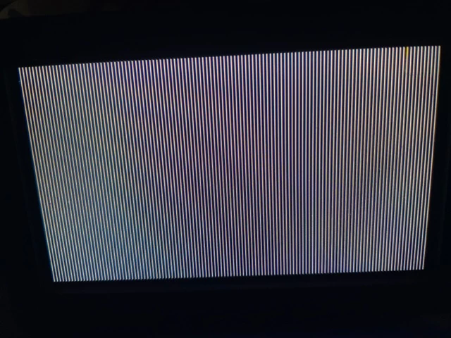
Hello friends, I am trying to better understand how data located at frame buffer address translates to what I am seeing on the LCD.
For example I have the following frame buffer data with mostly 0's and only the first value populated with a blue color.
static const uint32_t image_data[480] = {
 0x000000ff, 0x00000000, 0x00000000, 0x00000000, 0x00000000, 0x00000000, 0x00000000, 0x00000000, 0x00000000, 0x00000000, 0x00000000, 0x00000000,
.
.
 0x000000, 0x000000, 0x000000, 0x000000, 0x000000, 0x000000,
.
.
 0x00000000, 0x00000000, 0x00000000, 0x00000000, 0x00000000,
}
With LTDC PixelFormat set to LTDC_PIXEL_FORMAT_RGB888 - I get the following output on the LCD. A single blue line on the left-most side of the LCD.
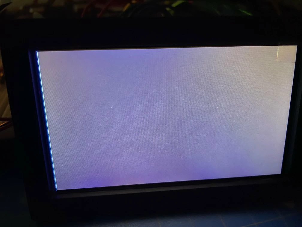 I think I can reason about the output but this still raises a question. I was expecting the first value from the frame buffer data to represent a single point on the screen not an entire line. How would I represent a single point if not like this?
I can reason about the color of the line since the value is 0x000000ff and the 2 least significant bits represent blue. The following 2 bits represent green, The next 2 bits represent red. I am assuming the 2 most significant bits are of no significance. I am just setting them to zero to explicitly represent the 32 bit number for each value expected by the array. And of course the rest of the zero values in the frame buffer translate to the rest of the screen being black.
So if each value represents a line on the LCD I modify my frame buffer data to set all values to blue. My expectation is a blue screen.
static const uint32_t image_data_IMG_4138[480] = {
 0x000000ff, 0x000000ff, 0x000000ff, 0x000000ff, 0x000000ff, 0x000000ff, 0x000000ff, 0x000000ff, 0x000000ff, 0x000000ff, 0x000000ff, 0x000000ff,
.
.
 0x000000ff, 0x000000ff, 0x000000ff, 0x000000ff, 0x000000ff, 0x000000ff, 0x000000ff,
.
.
 0x000000ff, 0x000000ff, 0x000000ff, 0x000000ff, 0x000000ff, 0x000000ff, 0x000000ff,
}
But the result is actually a consistent pattern of black and white lines. I am guessing there is something I am not understanding about how this frame buffer data is being translated to the LCD. Any hints? I have gone through the LTDC app note AN4861 and the slides for LTDC overview. Any additional material I can read the fix my understanding?