


load2005
Associate III
Oct 16, 2026 6:05 PM UTC
Question

Wrong conversion time on ADC and two samples instead of one.

Hello,

I am using NUCLEO-U5A5ZJ-Q evaluation board.
I have configured ADC1 to do a single conversion and a software start.
I want to measure ADC conversion time.

My main test code looks like this

while(1)
{

    HAL_ADC_Start_IT(&hadc1);        
    HAL_Delay(1);        
    HAL_ADC_Stop_IT(&hadc1);
    adc_value = hadc1.Instance->DR;    
}

I have added a test pin for debugging. To check with oscilloscope.
I set pin high inside HAL_ADC_Start_IT just before ADC enabled.
And I reset pin inside interrupt procedure ADC1_2_IRQHandler.

I have connected oscilloscope to ADC input pin directly to see 
sample begin. As ADC capacitor is connected to input and it has some charge
it is possible to see discharge curve on the screen.

Here is the picture.
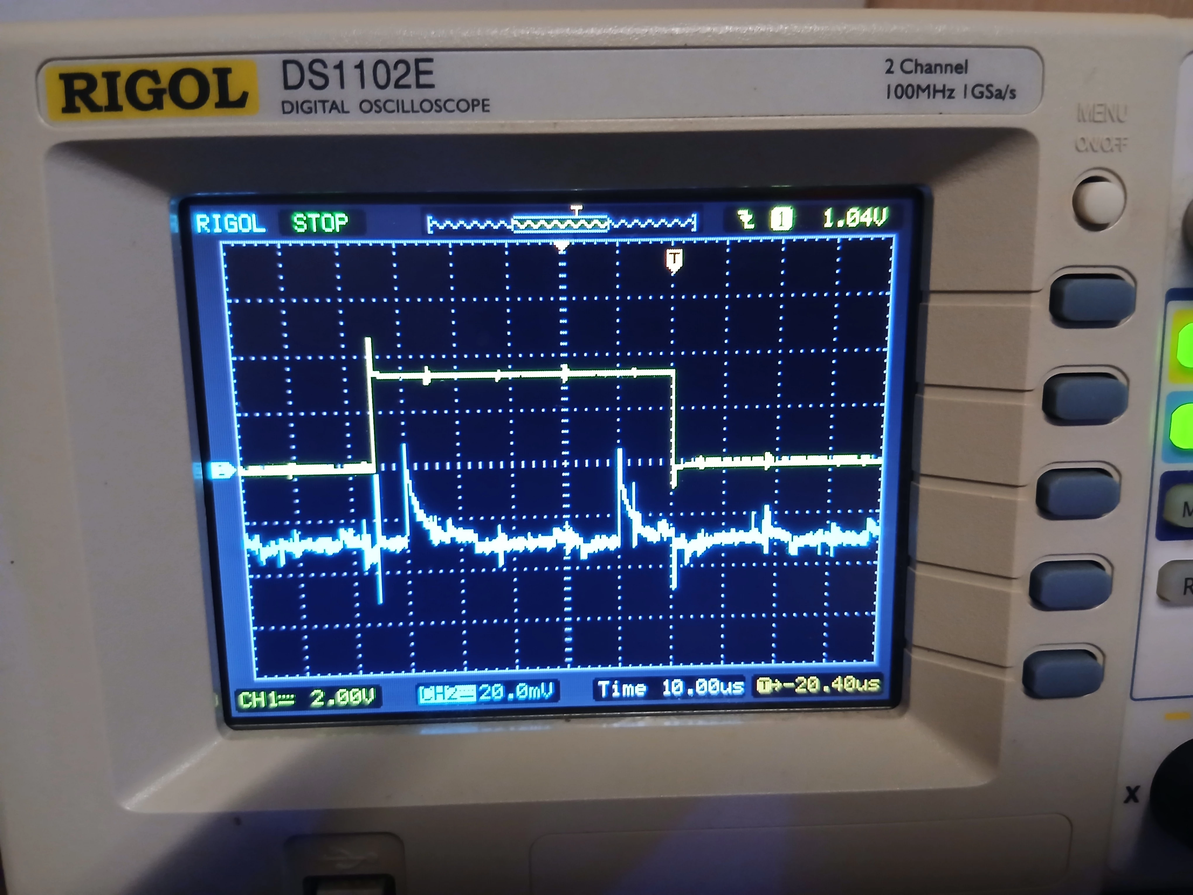
 

Yellow shows time between start and end of sampling.
Blue shows sampling begin (when capacitor is connected).

Why there are two discharge curves?
I have configured to do only one sample.
Also the timing is wrong.
I am using clock from external HSE.
It is 16MHZ. Divider is 32.
ADC is 12 bit so hold time is 12.5 clock cycles.
Sampling time is 5 clock cycles. (SPE is 0).
Now the time should be:
(12.5+5) * (1/16*32) = 35us

But the time on the screen is 55us.

I guess it is due to two samples but why there are two samples?

Here is screenshot from cube mx with ADC1 configuration.
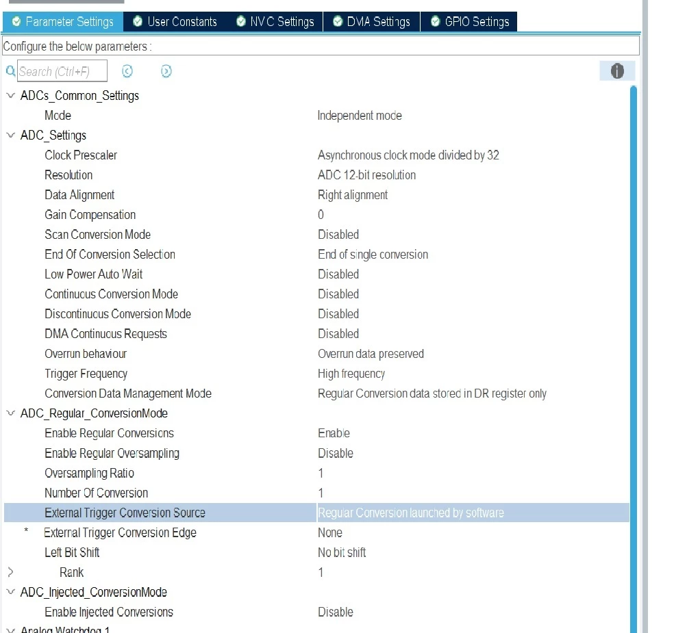
Thanks.
 

8 replies

TDK
Oct 16, 2026 6:14 PM UTC

One spike when the channel is connected, another when it is disconnected. Maybe, not 100% sure.

Timing is “wrong” because you are toggling a pin before to start and after the end of the sampling, not at the same time, so there is overhead in your measurement. Toggling a pin is not an accurate method of directly timing the ADC sampling rate.

Do 100 samples using DMA to a single buffer and time it using the toggle pin method, then do 1100 samples and time it. Take the difference and divide by 1000. That will be an accurate measurement of the sampling rate.

"If you feel a post has answered your question, please click ""Accept as Solution""."
load2005
load2005Author
Associate III
Oct 17, 2026 4:02 PM UTC

Hello,
Thanks for reply. 
Maybe you are right that second discharge is capacitor disconnection.
So the time between connect and disconnect is 40us.
It is sample time. In my setup it is 5 adc clocks so the time should be
5 * (1/16 * 32) = 10us.
So something is wrong here.

I set the pin imediately after 

MODIFY_REG(ADCx->CR, ADC_CR_BITS_PROPERTY_RS, ADC_CR_ADSTART);

in the  

__STATIC_INLINE void LL_ADC_REG_StartConversion(ADC_TypeDef *ADCx)

function. 
And reset the pin inside interrupt procedure.
So I think the time measure must be more or less accurate.
But still the time between samples is still large enough.

TDK
Oct 17, 2026 7:42 PM UTC

Let’s see what the RM has to say:

So sampling is 5 cycles according to you. And resolution of 12 bits is 15 cycles (not 12.5).

So 20 cycles total.

With a 16 MHz clock and /32 prescaler, this is 20 * 32 / 16 MHz = 40 us.

I think it may be doing 2 samples and not 1. Doing the timing exercise in my last post would give the correct timing. Or doing more than 1 sample.

"If you feel a post has answered your question, please click ""Accept as Solution""."
load2005
load2005Author
Associate III
Oct 18, 2026 5:34 PM UTC

Hello,

Yes you are right. I choosed wrong conversion time from ADC4 table.
The whole time is 40us. It is exact time between discharge curves.
But why second discharge curve is present and why there is additional 
10us delay before interrupt?
Only one iterrupt is generated after conversion I checked that.
If second discharge curve is sampling why there is no interrupt?

I have checked that pins set/reset takes about 200ns so it does not 
affect the measuremetns much.
Currently I want to understand why second discharge curve exists.
Will program DMA later to measure multiple adc sample time.

load2005
load2005Author
Associate III
Oct 20, 2026 5:59 PM UTC

I have made a ADC sampling using DMA.
Here is the screenshot with two samples.


After second sample at the end there are additional two discharge curves.
I think maybe they are not related to sampling but capacitor is connected 
for other reasons.
Still there is a 10us delay after second sample and interrupt call.
I can't find in the datasheed the latency.
How this latency can be called?
Thanks.
 

TDK
Oct 20, 2026 6:49 PM UTC

It would help to keep one post per question. There are too many questions here, the goalposts keep moving. I have answered the first question about “wrong conversion time on ADC”. In my experience these types of ongoing questions never lead to a “accepted answer” so it’s hard to find motivation to explain every new question as it comes up.

"If you feel a post has answered your question, please click ""Accept as Solution""."
waclawek.jan
Super User
Oct 22, 2026 9:30 AM UTC

The STM32 ADCs are overly complicated beasts and you are casually setting it up using another overly complicated beast, which is the Cube/HAL/CubeMX combination.

Assuming you stick here to the simple case, as TDK suggested above, start with reading out all ADC registers’ content and deciphering the setting using the registers description in RM. This is not to say that the behaviour you’ve observed necessarily can be explained by reading the RM - ST omits vital information they deem “unimportant to user” - but that’s the absolute minimum effort.

JW

Ozone
Principal
Oct 22, 2026 10:12 AM UTC

> ... ST omits vital information they deem “unimportant to user” - but that’s the absolute minimum effort.

Very likely.
Who knows what the S&H capacitor and the input pins are switched to after a sequence is finished, perhaps causing the observed spike.
We don’t know, and honestly, I don’t care or obsess about it as long as the “user interface” is described correctly and sufficiently.