

Writing SPI driver for digital potentiometer issue with LSB/MSB order
Hello. I have AD5270 10 bit digital potentiometer and I am writing SPI driver for it.
The wiring is as following:
STM32F407 AD5270
+3.3V ->VDD
GND ->VSS
SPI1_MISO -> (Not currently wired with SDO, SDO is pulled up with 10k)
SPI1_MOSI -> DIN
SPI1_CLK -> SCLK
SPARE_GPIO -> CS
STSM32 SPI configuration:
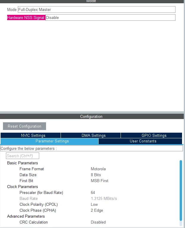
As you can see form above CPOL = 0 and CPHA = 1 (2 edge) this is required for AD5270.
According to AD5270 documentation:
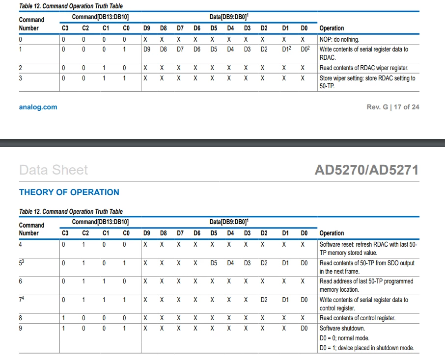
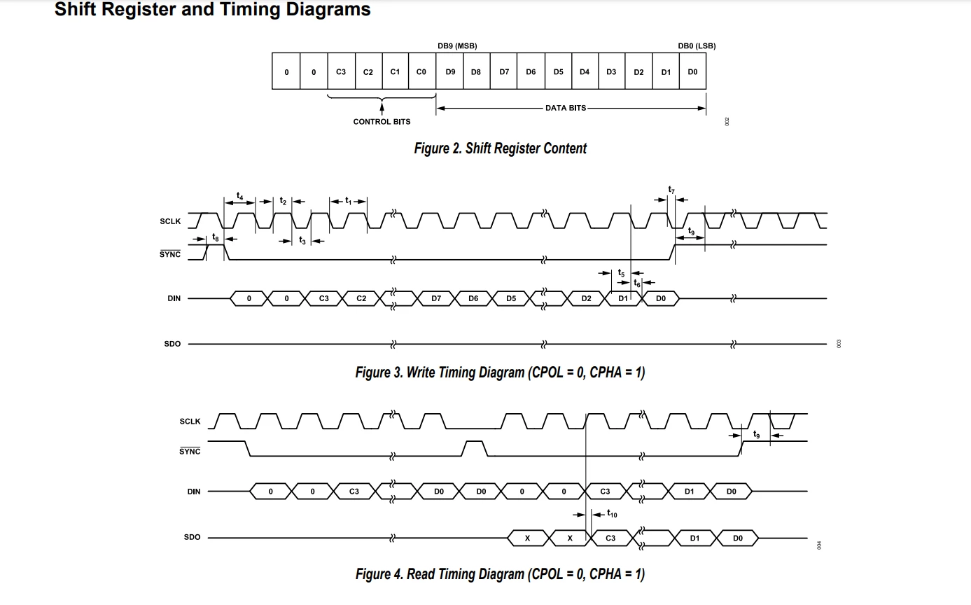
As you can see from the first image, I am mainly interested in Command number 1 (Write contents of serial register data to RDAC)
C3 C2 C1 C0
0 0 0 1
I am now trying to build a correct frame for writing 10 bit value to set the potentiometer value

I am a little confused regarding MSB/LSB. Could someone clarify How do I build correct frame and which order do I need to send bytes. At the moment, I have written this function:
//WRITE_RDAC = (1<<2),

void AD5270_WRITE_RDAC(uint16_t value){

// first 2 bytes are 0, then 0 0 0 1 D9 D8,

// so the frame look like (when value = 16)

// 0 0 0 0 0 1 0 0 0 0 0 1 0 0 0 0

// so the frame look like (when value = 2)

// 0 0 0 0 0 1 0 0 0 0 0 0 0 0 1 0

	if(value > 1024){

 DEBUG_PRINT("Input value out of bounds \n");

 return;

	}

	uint8_t spi_data[2] = {WRITE_RDAC,value};

	AD5270_CS_Enable();

	HAL_SPI_Transmit(&hspi1,spi_data, 2, 0xff);

	AD5270_CS_Disable();

}
Logic analyzer settings:
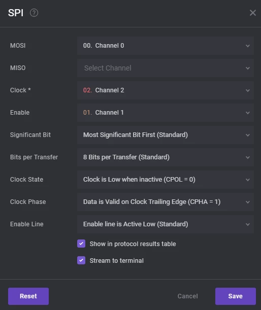
I tried to execute the following command:
AD5270_WRITE_RDAC(16);And I see on the logic analyzer:
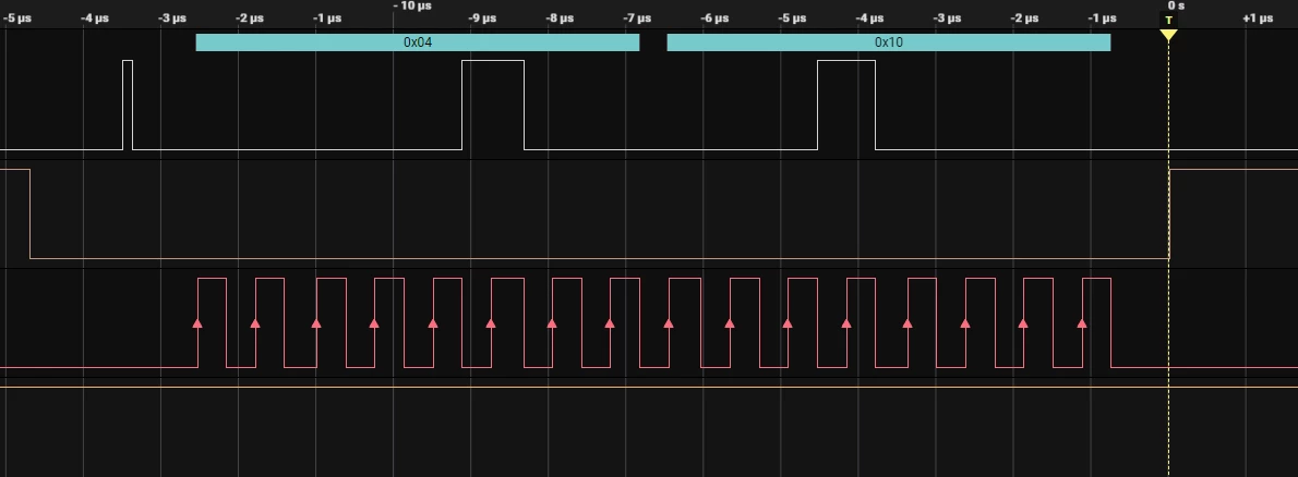
When I try to send:
AD5270_WRITE_RDAC(2);The signal looks like:
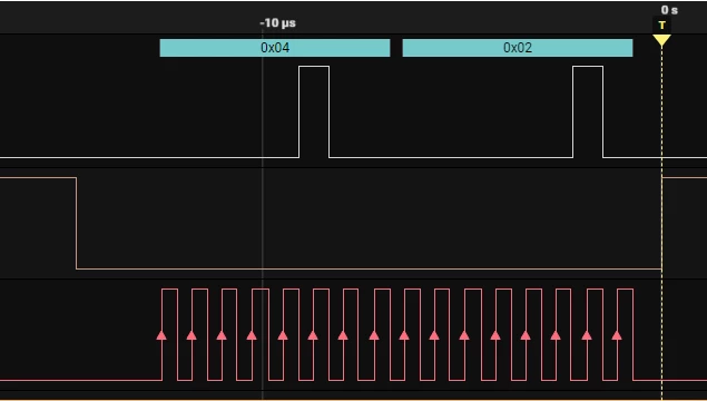
I just want to understand whether my frame is incorrect or I should be looking at hardware issues (maybe the chip is faulty or something else). I am monitoring Wiper (W pin on the AD5270) using digital multimeter and it does not change when I send the commands. I expect the resistance to change when I write different values to RDAC. The resistance is always set to 900Ohms and its not changing.
