

JCorl.1
Senior
October 6, 2021
Solved

Why does the debugger not respond after UE bit is set for UART4?

  • October 6, 2021
  • 10 replies
  • 2622 views

Hello everyone!

My setup uses a STM32407VG. I have been using for some time now and have gotten used to how to read the datasheet and use some of features. Today I am trying to get UART4 transmitting some data.

Here is how I went about getting it all setup:

  1. UART4 TX can be used on PC10. Therefore we must enable the AHB1 to turn on GPIOC.
  2. The UART4 module itself is one APB1 so that must be enabled as well.
  3. Via MODER, OTYPE, OSPEEDR PUPDR, I also make sure its push pull, disabled pullups and output speed is medium. Pretty sure I don’t need to do this but I did it anyway!
  4. Via AFR[1], I set the MODER register for GPIOC to be as alternate function mode.
  5. My system clock is running at 168MHz (verified from previous projects), and my APB1 PCLK1 is 42MHz. Via the BRR, I set the baudrate and used this formula: BRR = [pclk + (baud/2)] / baud. I set CR1 to 0x04 to set the TE bit and other parameters.
  6. Here is where I get some problems, I set the UE bit in CR1.

I did step through the debugger (via STLINK) and it appears I am setting all of the correct bits. But when I land on that UE bit, I get the error (in the console) Target is not responding, retrying… until it times out. Below is a code snippet.

/* UART Functions */
 
void UART4_Config()
 
{
 
	// Enable GPIO C
 
	RCC->AHB1ENR |= RCC_AHB1ENR_GPIOCEN;
 
 
	// Enable the UART (PC10=TX PC11=RX)
 
	RCC->APB1ENR |= DKO_UART4_ENABLE;
 
 
	// UART4 TX PIN
 
	GPIOC->MODER &= ~(GPIO_MODER_MODE10); // Clear pin mode field
 
	GPIOC->MODER |= GPIO_MODER_MODER10_1; // Set pin mode field as alternate
 
	GPIOC->OTYPER &= ~(GPIO_OTYPER_OT10); // Clear output type field (push-pull by default)
 
	GPIOC->OSPEEDR &= ~(GPIO_OTYPER_OT10); // Clear output speed field (low by default)
 
	GPIOC->OSPEEDR |= GPIO_OSPEEDR_OSPEED10_0; // Set to medium speed
 
	GPIOC->PUPDR &= ~(GPIO_PUPDR_PUPD10); // Clear pullup/ pulldown mode field (none as default)
 
	GPIOC->AFR[1] &= ~(1U << 8); // Set alternate function to be AF8, bit 8
 
	GPIOC->AFR[1] &= ~(1U << 9); // Set alternate function to be AF8, bit 9
 
	GPIOC->AFR[1] &= ~(1U << 10); // Set alternate function to be AF8, bit 10
 
	GPIOC->AFR[1] |= (1U << 11); // Set alternate function to be AF8, bit 11
 
 
	// UART4 SPECIFIC CONFIG
 
	UART4->BRR = 2188; // Set baudrate to be 19200; formula is BRR = [pclk + (baud/2)] / baud
 
	UART4->CR1 = (1U << 3); // Set the TE bit (transmitter enable bit)
 
	UART4->CR1 |= (1U << 13); // Set the UE bit (uart enable bit)
 
}

I never used a UART other than on things like BASIC STAMP, PICAXE, and ARDUINO. It is a little more setup with bare metal STM32F407 but it looked pretty doable. Any hints would be greatly appreciated! Thanks for your time!

This topic has been closed for replies.
Best answer by TDK

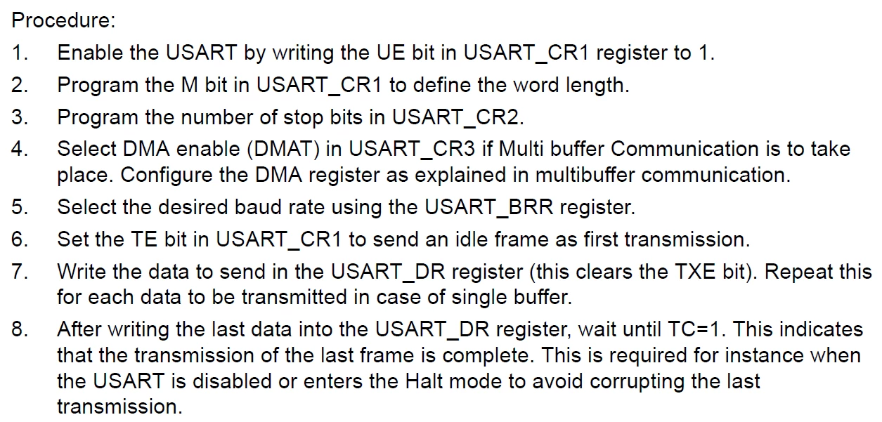
Might not be it, but the RM says to enable UE first, then do everything else.

0693W00000FBg7VQAT.png 

Code is easier to read if you use standard defines than custom bits

UART4->CR1 |= (1U << 13); --> UART4->CR1 |= USART_CR1_UE;

Custom board? Make sure PC10 isn't connected to anything else that will disrupt the debugger. Set it as GPIO and toggle it.

10 replies

TDK
TDKBest answer
October 6, 2021

Might not be it, but the RM says to enable UE first, then do everything else.

0693W00000FBg7VQAT.png 

Code is easier to read if you use standard defines than custom bits

UART4->CR1 |= (1U << 13); --> UART4->CR1 |= USART_CR1_UE;

Custom board? Make sure PC10 isn't connected to anything else that will disrupt the debugger. Set it as GPIO and toggle it.

"If you feel a post has answered your question, please click ""Accept as Solution""."
JCorl.1
JCorl.1Author
Senior
October 6, 2021

Hey thanks for the reply! I properly corrected the order and also used the standard defines where it was missing.

void UART4_Config()
{
	// Enable GPIO C
	RCC->AHB1ENR |= RCC_AHB1ENR_GPIOCEN;
 
	// UART4 TX PIN GPIO SETUP
	GPIOC->MODER &= ~(GPIO_MODER_MODE10);		 // Clear pin mode field
	GPIOC->MODER |= GPIO_MODER_MODER10_1;		 // Set pin mode field as alternate
	GPIOC->OTYPER &= ~(GPIO_OTYPER_OT10);	 	 // Clear output type field (push-pull by default)
	GPIOC->OSPEEDR &= ~(GPIO_OTYPER_OT10); 	 	 // Clear output speed field (low by default)
	GPIOC->OSPEEDR |= GPIO_OSPEEDR_OSPEED10_0;	 // Set to medium speed
	GPIOC->PUPDR &= ~(GPIO_PUPDR_PUPD10);		 // Clear pullup/ pulldown mode field (none as default)
	GPIOC->AFR[1] &= ~(1U << 8); 			 // Set alternate function to be AF8, bit 8
	GPIOC->AFR[1] &= ~(1U << 9);				 // Set alternate function to be AF8, bit 9
	GPIOC->AFR[1] &= ~(1U << 10);				 // Set alternate function to be AF8, bit 10
	GPIOC->AFR[1] |= (1U << 11);				 // Set alternate function to be AF8, bit 11
 
	// STEP 0 - Enable the bus to UART4
	RCC->APB1ENR |= DKO_UART4_ENABLE;
 
	// STEP 1 - Enable the UART (PC10=TX PC11=RX) by setting the UE bit (uart enable bit)
	UART4->CR1 |= (USART_CR1_UE);
 
	// STEPS 2, 3, and (not 4) - sets the M, SOP, and TE bits
	UART4->CR1 |= (USART_CR1_TE);
 
	// STEP 6 - Set baudrate to be 19200; formula is BRR = [pclk + (baud/2)] / baud
	UART4->BRR = 2188;
}

Yes its a custom board. I checked to make sure I was able to toggle it when its configured as an output (push-pull). I got alternating signals when toggling it in a while loop. So the pin seems to be okay. I should note there is a 1kohm pullup on it for a different configuration in my project (open drain mode for 1-wire bit banging). It doesn't seem to hurt it when in strictly output mode. Since UART is configured as push-pull as well, I think its okay.

When I run the altered code, I can set the UE bit fine now. The target does not respond when it executes its last line (trying to return from the function). So I tried commenting in and out some code. I found that UART4->BRR was causing problems with the debugger. Maybe changing the baudrate messes up debugging? It seems so. So I let the code run and ran an infinite while loop..... I finally get data! But garbage data. I am using my protocol analyzer within the logic analyzer I am using and it keeps getting "framing error". Hey I am closer :)

JCorl.1
JCorl.1Author
Senior
October 6, 2021

Hmmmm yeah there must be something weird going on. Okay so call me crazy but I hear clicking in the MCU. You know when like power MOSFETs are shorting and constantly are turning on and off due to some weird error condition? I hear something similar. It stop when comment out the uart config function I made. Going to poke around some more to see what else I find out.

TDK
October 6, 2021

You're still not doing the correct order of initialization. TE should be last.

I would test the code on known good hardware such as a nucleo board. Upload your schematic if you want.

"If you feel a post has answered your question, please click ""Accept as Solution""."
JCorl.1
JCorl.1Author
Senior
October 6, 2021

Sorry about that! I was careless with the pasting of the up to date code. Here it is:

void UART4_Config()
{
	// Enable GPIO C
	RCC->AHB1ENR |= RCC_AHB1ENR_GPIOCEN;
 
	// UART4 TX PIN GPIO SETUP
	GPIOC->MODER &= ~(GPIO_MODER_MODE10);		 // Clear pin mode field
	GPIOC->MODER |= GPIO_MODER_MODER10_1;		 // Set pin mode field as alternate
	GPIOC->OTYPER &= ~(GPIO_OTYPER_OT10);	 	 // Clear output type field (push-pull by default)
	GPIOC->OSPEEDR &= ~(GPIO_OTYPER_OT10); 	 	 // Clear output speed field (low by default)
	GPIOC->OSPEEDR |= GPIO_OSPEEDR_OSPEED10_0;	 // Set to medium speed
	GPIOC->PUPDR &= ~(GPIO_PUPDR_PUPD10);		 // Clear pullup/ pulldown mode field (none as default)
	GPIOC->AFR[1] &= ~(1U << 8); 			 // Set alternate function to be AF8, bit 8
	GPIOC->AFR[1] &= ~(1U << 9);				 // Set alternate function to be AF8, bit 9
	GPIOC->AFR[1] &= ~(1U << 10);				 // Set alternate function to be AF8, bit 10
	GPIOC->AFR[1] |= (1U << 11);				 // Set alternate function to be AF8, bit 11
 
	// STEP 0 - Enable the bus to UART4
	RCC->APB1ENR |= DKO_UART4_ENABLE;
 
	// STEP 1 - Enable the UART (PC10=TX PC11=RX) by setting the UE bit (uart enable bit)
	UART4->CR1 |= (USART_CR1_UE);
 
	// STEP 2 - Set the M bit
	UART4->CR1 |= (USART_CR1_M);
 
	// STEP 3 - Set the stop bits
	UART4->CR1 |= (USART_CR2_STOP_1);
 
	// STEP 4
	// NONE
 
	// STEP 5 - Set baudrate to be 19200; formula is BRR = [pclk + (baud/2)] / baud
	UART4->BRR = 4376;//2188;
 
	// STEP 6 - Set the TE bit
	UART4->CR1 |= USART_CR1_TE;
}

I think the 1kohm pullups really messed up the UART. Took some hot air and removed them, did the trick. Now I am finally getting some clear data. Thank you for the help! Where can I place some money to buy you a coffee? :p

Tesla DeLorean
Guru
October 6, 2021

If the purpose of using register level coding is to be efficient, you might consider folding the multiple LOAD/STORE (RMW) operations to achieve that end.

The Compiler can also pre-compute constants, so math doesn't become part of the code, improving clarity, and eases porting/changes.

Tips, Buy me a coffee, or three.. PayPal Venmo (See Profile) Up vote any posts that you find helpful, it shows what's working..
JCorl.1
JCorl.1Author
Senior
October 6, 2021

Oh interesting. I will read up on this. The register level coding is honestly more for education. Though I have been using it more and more for my own projects. I dunno I find it easier to understand a bottom up approach when learning. Starting with the HAL, I felt disconnected.

JCorl.1
JCorl.1Author
Senior
October 7, 2021

I actually didn't know about these. Are they portable?

Yes I am not sure why the pullups were causing the issue. I have nothing else connected to that tx line. I will look into it more as I play around.

Thanks again for the help! I am already paying it forward by helping someone understand ADC circuits and opamps tomorrow over a Discord call so rest assured the good deed will be paid back :)

JCorl.1
JCorl.1Author
Senior
October 8, 2021

As an update, I got the RX portion working as well. Though I do have another question about UART in general but I will create a new thread for this.
