Dave Nadler
Senior III
October 23, 2018
Solved

Where is timer clock source documented?

  • October 23, 2018
  • 10 replies
  • 5751 views

For example timer A: is it low-speed (APB1) 'APB1 timer clock' or high-speed APB2 'APB2 timer clock'?

I read the timer and RCC sections but could not figure this out...

Can you tell me where this is documented?

Thanks!
This topic has been closed for replies.
Best answer by Tesla DeLorean

Other STM32 parts, where the RM covers a few dozen varied ICs, you get referred to the DS

0690X000006CF3rQAG.jpg

but also

0690X000006CF3wQAG.jpg

10 replies

Tesla DeLorean
Guru
October 23, 2018

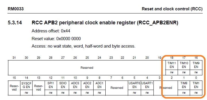
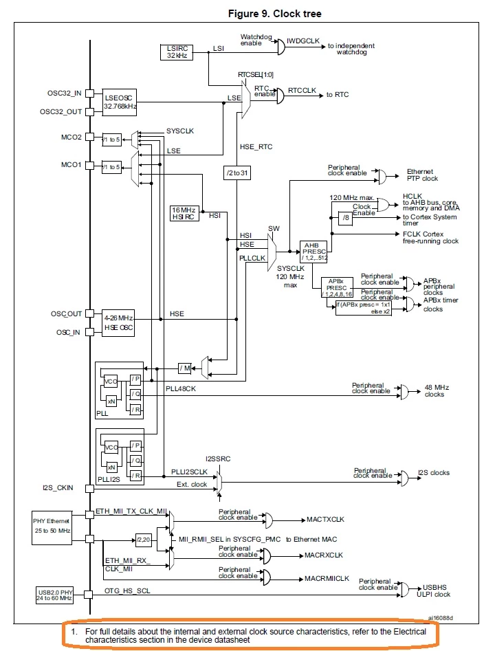
There is typical a Clock Tree diagram, a diagram of which TIM/peripherals are on which bus, and the RCC_APBxENR registers also infer which TIM is on each bus based on which bus clock that needs to be enabled.

Tips, Buy me a coffee, or three.. PayPal Venmo (See Profile) Up vote any posts that you find helpful, it shows what's working..
waclawek.jan
Super User
October 23, 2018

What is timer A?

JW

Dave Nadler
Senior III
October 23, 2018

Arbitrary timer A... WHERE is diagram showing which peripheral is on which clock tree?

I just found the timer clock sources in tabular form in the datasheet (not in reference manual where I searched).

Next stop - is a #define for the timer clock frequency output by the CubeMX tool for each timer?

Tesla DeLorean
Guru
October 23, 2018

ST likes diagrams for the kidz that can't read good and stuff, here from a Reference Manual for an arbitrary STM32 part.

0690X000006CF3NQAW.jpg

Tips, Buy me a coffee, or three.. PayPal Venmo (See Profile) Up vote any posts that you find helpful, it shows what's working..
Tesla DeLorean
Tesla DeLoreanBest answer
Guru
October 23, 2018

Other STM32 parts, where the RM covers a few dozen varied ICs, you get referred to the DS

0690X000006CF3rQAG.jpg

but also

0690X000006CF3wQAG.jpg

Tips, Buy me a coffee, or three.. PayPal Venmo (See Profile) Up vote any posts that you find helpful, it shows what's working..
Dave Nadler
Senior III
October 23, 2018

Yup, missed that bit in the Device Overview block diagram...

waclawek.jan
Super User
October 23, 2018

Note, that these are SoC, i.e. IP modules thrown relatively loosely together, and sewn by a fabric of buses and interconnections. Now the documentation follows this pattern, i.e. the IP modules (e.g. timer, SPI, UART, etc.) have their own chapter, but the interconnections are documented poorly and pieces of information of this character are scattered around the RM. In some families' RMs there is an Interconnection chapter, but that usually leaves lots of these information out too.

In other words, yes, you ought to read the manual back to back (or at least all chapters which are related to modules you are using) (oh, yes, the dreaded reading!)

JW

Pavel A.
October 23, 2018

CubeMX can show the clocks tree very nicely, if you use it.

/* Some time ago there was a request to display the clock and frequency info in CubeMx GUI for timers, to save users time from digging in the manuals ... but given the overall situation, I'm not holding my breath */

-- pa

Khouloud GARSI
ST Employee
October 23, 2018

Hi @Dave Nadler​ ,

You may have a look on "RCC_APB1ENR" and "RCC_APB2ENR" registers in the reference manual.

Example: "RCC_APB1ENR " register shows the peripherals connected to the APB1 bus (screenshot taken from STM32F2 RM).

0690X000006CF5xQAG.png

Khouloud.

Dave Nadler
Senior III
October 23, 2018

PA, the nice clock diagram in CubeMX does not show which timers are on which clock, which was the original question. In the reference for the particular part I was looking at, the information was not in the RCC section nor the timer section, nor is there an "interconnection section". But it is in the datasheet, and in the overview block diagram. Thanks JW and Clive!