ykn
Associate III
July 27, 2022
Solved

where is the QSPI CS# Pin is used QSPI library

0693W00000QMHONQA5.pnghi,

this is the first time i have used QSPI library, I have to use external flash in QSPI mode.

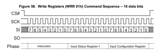
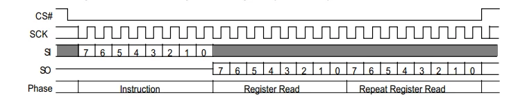
In the data sheet it is given that, CS# pin should be low until command instruction 16bit data will pass. as shown ablove.

but when executing command the CS# Pin perform HIGH-LOW_HIGH and again did the same thing at the timing of writing. this should not happen. asper data it low at command insertion and data writing.

ihave check ON CRO.

my question where is the CS# micro, so that i can manage to write.

i know this could be stupid question.

thanking you.

 if (HAL_QSPI_Command(&QSPIHandle, &s_command, HAL_QPSI_TIMEOUT_DEFAULT_VALUE) != HAL_OK)
	 {
	 return QSPI_ERROR;
	 }

This topic has been closed for replies.
ykn
yknBest answer
Associate III
July 30, 2022

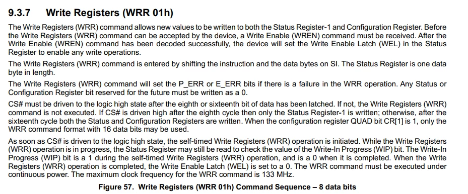
For enabling the QSPI mode, you need to set QEN bit of configuration bit and for that you have to send write enable command followed by 16 bit value of status register and configuration register. In that sequence CS# should be low.

given in data sheet. i have attached screen shot0693W00000QMWw0QAH.png0693W00000QMWw5QAH.pngbut when I write code for enabling command given below
int32_t QSPI_EnterQPIMode(QSPI_HandleTypeDef *Ctx)
{
	QSPI_CommandTypeDef s_command;
	uint8_t reg_data[] = {0x02, 0x02};
	 /* Enable write operations */
	 s_command.InstructionMode = QSPI_INSTRUCTION_1_LINE;
	 s_command.Instruction = 0x01; /* equal on both memory types */
	 s_command.AddressMode = QSPI_ADDRESS_NONE;
	 s_command.AlternateByteMode = QSPI_ALTERNATE_BYTES_NONE;
	 s_command.DataMode = QSPI_DATA_NONE;
	 s_command.DummyCycles = 0;
	 s_command.NbData = 2;
	 s_command.DdrMode = QSPI_DDR_MODE_DISABLE;
	 s_command.DdrHoldHalfCycle = QSPI_DDR_HHC_ANALOG_DELAY;
	 s_command.SIOOMode = QSPI_SIOO_INST_EVERY_CMD;
 
	 if (HAL_QSPI_Command(&QSPIHandle, &s_command, HAL_QPSI_TIMEOUT_DEFAULT_VALUE) != HAL_OK)
	 {
	 return QSPI_ERROR;
	 }
 
	 if (HAL_QSPI_Transmit(&QSPIHandle, reg_data, HAL_QPSI_TIMEOUT_DEFAULT_VALUE) != HAL_OK)
	 {
		 return QSPI_ERROR;
	 }
 
	 return QSPI_OK;
}

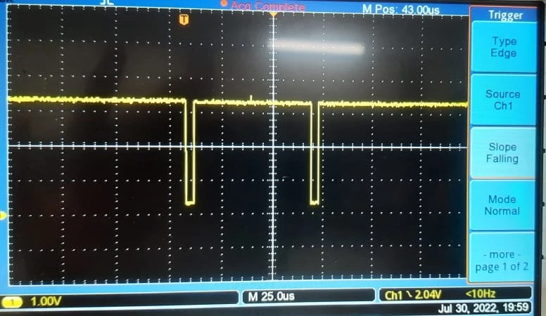
the CS# pin get two time HIGH_LOW sequence, where in datasheet(screen shot above) it should be done in consecutive.

CS# pin screen shot for enterQPI mode.0693W00000QMWwAQAX.jpgi think because of this i am not getting proper result, so if I manipulate CS pin, result would be proper. correct if am wrong .
thanking you

6 replies

Tesla DeLorean
Guru
July 27, 2022

It's controlled properly/directly by the Peripheral, and via the AF setting of the associated pin.

The data sheet would list those pins usable for this.

The CS would be held low for Data transfer if you've got some DataMode and NbBytes set in the device instance (QSPIHandle), and you subsequently issue a HAL_QSPI_Receive()

Note that you can have a more open-ended/protracted transaction using the HAL_QSPI_AutoPolling() function, which waits for specific conditions in the read data to be met, and then dumps the CS

There's probably a section in the Reference Manual on this..

Tips, Buy me a coffee, or three.. PayPal Venmo (See Profile) Up vote any posts that you find helpful, it shows what's working..
ykn
yknAuthor
Associate III
July 30, 2022

i have search all the code, but i dint see any CS# low micro.

and there is no such thing in reference manual.

please provide if you got this.

thanking you.

Tesla DeLorean
Guru
July 30, 2022

The questions lose something in translation

Some aspects controlled in configuration

 hQspi->Init.ChipSelectHighTime = QSPI_CS_HIGH_TIME_4_CYCLE; /* Min 50ns required after non Read command */

 hQspi->Init.ClockMode     = QSPI_CLOCK_MODE_0;

 hQspi->Init.FlashID      = QSPI_FLASH_ID_1;      /* Default value at start, can be changed dynamically using BSP_QSPI_SetFlashID() */

The peripheral owns the pin control

 /* QSPI BK1 CS GPIO pin configuration */

 gpio_init_structure.Pin    = QSPI_BK1_CS_PIN;

 gpio_init_structure.Pull   = GPIO_PULLUP;

 gpio_init_structure.Alternate = QSPI_BK1_CS_PIN_AF;

 HAL_GPIO_Init(QSPI_BK1_CS_GPIO_PORT, &gpio_init_structure);

These setting use by HAL_QSPI_Command and HAL_QSPI_Receive/Transmit ultimately determine how the peripheral holds the NCS signal. Normal behaviour is NCS drops at the beginning of the command dispatch, and then raises it at the end of the data transaction.

 s_command.AddressSize    = QSPI_ADDRESS_32_BITS;

 s_command.AlternateBytes = 4; 

s_command.DummyCycles   = 8;

s_command.NbData      = Size;

It is not a GPIO you can control manually, it is driven by the peripheral's state-machine, based on settings/parameters configured.

Tips, Buy me a coffee, or three.. PayPal Venmo (See Profile) Up vote any posts that you find helpful, it shows what's working..