

MMust.5
Senior
May 21, 2022
Solved

Where is port A registers configured for pins 13 and 14 to configure SWD?

  • May 21, 2022
  • 14 replies
  • 3926 views

STM32F407VGT6

Here is my code:

#include "main.h"

int main(void)

{

RCC->AHB1ENR|=RCC_AHB1ENR_GPIOAEN;

 while (1)

 {

 }

}

For port A registers (pins 13 and 14) is the configuration done in the IDE? In the code, I did not find the configuration of port A registers, but SWD still works.

What settings are needed to install SWD on pins 13 and 14 of port A?

I looked at the GPIOA_MODER register, it looks like this: 1010 1000 0000 0000 0000 0000 0000 0000

It turns out pins 13 and 14 are set to Alternate function mode.

For some reason, pin 15 of port A is also set to Alternate function mode, although pin 15 of port A is a general purpose pin.

I cleared those GPIOA->MODER=0; bits, but they are not overwritten when the IDE is restarted.

I have to erase the whole chip to get into it.

In the code, I did not find where port A is configured, but if the configuration occurs through the IDE, then why are the bits not restored after I erase them GPIOA->MODER=0;

------------------------

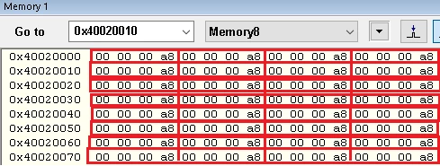
Port A registers start at address 0x40020000.
0693W00000NqPK7QAN.png 

This topic has been closed for replies.
Best answer by Piranha

With the "normal" reset mode the MCU hardware sets the register to reset value, the CPU starts running, your firmware sets the register to zero and the debugger looses the connection almost immediately. With the "connect under reset" mode the debugger connects to the MCU while still keeping it in a reset state, in which the CPU is not running and therefore the firmware cannot interfere.

Nothing is broken here and everything works as it should.

14 replies

Andreas Bolsch
Lead III
May 21, 2022
MMust.5
MMust.5Author
Senior
May 21, 2022

I don't think this is an answer, but thanks for your opinion anyway.

I didn't get many answers to my questions.

So I will search myself or someone will answer.

Pavel A.
May 21, 2022

Short answer: the debugger itself configures these pins via the debug module of the MCU.

Piranha
Principal III
May 22, 2022

Actually everything is explained pretty clearly in that German forum...

Reset values are not configured anywhere, but are fixed in hardware and documented in the reference manual. PA15, PB3, PB4 are additional pins for SWO and/or JTAG. So you have figured out that you need GPIOA->MODER to be set to 0x28000000. Then why are you setting it to zero? And is it so hard to understand that from that point you have reconfigured also the PA13, PA14 and therefore the debugger doesn't work anymore?

MMust.5
MMust.5Author
Senior
May 22, 2022

>>So you have figured out that you need GPIOA->MODER to be set to 0x28000000. Then why are you setting it to zero?

After this code GPIOA->MODER=0; and restarting the IDE, all bits of the GPIOA->MODER register are restored to A800 0000 - this is the reset value.

But I can only enter the Microcontroller after restarting the IDE using Connect under reset.

I'm trying to understand what was not restored to the default settings after this code GPIOA->MODER=0;

For this reason, I am looking for where reset values ​​are stored for microcontroller ports.

Maybe I should look for something else, I don't know.

Do not touch these bits and nothing will break?

I want to understand why it broke.

Piranha
PiranhaBest answer
Principal III
May 22, 2022

With the "normal" reset mode the MCU hardware sets the register to reset value, the CPU starts running, your firmware sets the register to zero and the debugger looses the connection almost immediately. With the "connect under reset" mode the debugger connects to the MCU while still keeping it in a reset state, in which the CPU is not running and therefore the firmware cannot interfere.

Nothing is broken here and everything works as it should.

MMust.5
MMust.5Author
Senior
May 22, 2022

>>your software sets the register to zero and the debugger looses the connection almost immediately.

Why, after restarting the IDE, can I not enter the MCU in normal mode using the IDE? (Without Connect under reset).

The GPIOA->MODER register after restart takes the standard reset value.

>> while still keeping it in a reset state, in which the CPU is not running 

In the reset state, the CPU is not running?

All registers are set to default, but the CPU is not running? I thought that the processor needs the standard values ​​​​of registers for normal operation.

>>and therefore the software cannot interfere.

0693W00000NqPu0QAF.pngI am trying to run the IDE in Debug without Downloading mode. The IDE doesn't interfere, doesn't overwrite anything.

The second time I'm not trying to upload the wrong code (GPIOA->MODER=0;) to the Microcontroller.

The GPIOA->MODER register is set to the standard value after the restart, but I cannot enter the Microcontroller through the IDE in normal mode (Without Connect under reset).

Piranha
Principal III
May 22, 2022

My previous comment talks about the CPU and software (firmware) on the MCU, not the IDE. Debugging with or without downloading doesn't matter here. Yes, the CPU starts executing instructions only after the reset is released and the MCU exits the reset state.

