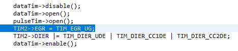
When timer is enabled it creates initial DMA request even CNT is 0
I want to generate waveform for 8 channel WS2812 leds using STM32F103. This device uses pulse with to transfer bits.. The longer pulse means 1, the shorter means 0..
Because I want to generate 8 channel wavefrm, I configured 3 DMA's, one moves 0xFF to GPIO, one moves value from RAM to GPIO, and the third one moves 0x00 to GPIO.. The timing is generated by TIM2's CC1, CC2 and TIM2's update events.. That way, CC1 moves 1s to GPIO, CC2 moves Data to GPIO, update moves 0s to GPIO.
TIM3 is connected as slave to the TIM2. In each TIM2 update, TIM3 counts up. It is configured as oen pulse, so that when TIM3 reaches ARR, it disables it self.. TIM2 is connected as slave to TIM3 as gated mode.. When TIM3 starts/stops TIM2 starts/stops as well.. This way I limit the transfers, and after final TIM2 update, which moves 0 to the GPIO, system stops until I reenable the timer.
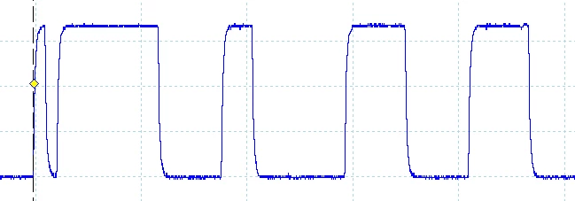
Waveform for 8 channels is generated correctly but the very first pulse is generated wrong.. It looks like TIM2 generates request for all 3 DMA's as soon as it is enabled, even before CC1, CC2 and update is generated. That casues very first transfers be done with respect to DMA's priorities. The remaining pulses are generated as expected..
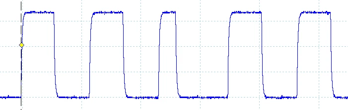
To make it easier, I made a waveform with 5 pulses.. ARR of TIM3 is set to 4..
This is correct transfer of 11011
 This is the very first transfer whose first bit is scrambled because of initial DMA request:
When I do not enable DMA requests, enable the TIM3, disable it, reset TIM2->CNT and TIM3->CNT, enabling DMA request, reanable TIM3 the very first pulse is also generated correctly.. As I mentined the remaining cycles are correct.. Like the following code:
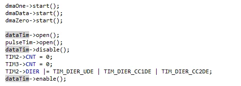 I am using my own library. However, I think the names are self evident..
I've a workaround, but I want to understand why TIM2 generates DMA request when it is enabled even if the counter has not reached configured state..