What is a good buffering method for real time DSP (I2S, DMA) ?
I have a custom board with an STM32F412re and a TLV320aic Codec, where the Codec is in Master mode and the I2S2 Interface of the STM32 in Full Duplex Slave mode.
So far I have the I2S2 interface configured to send and receive the data over DMA.
On DMA transfer complete Interrupt I copy the input buffer (uint16_t) to the output buffer.
This way I have a passthrough of the audio signal.
Now I also implemented the float32_t FIR example from CMSIS/DSP. I have verified, that the FIR filter works (amplitude shows low-pass characteristic). However I am seeing (and hearing) that the audio signal has gaps.
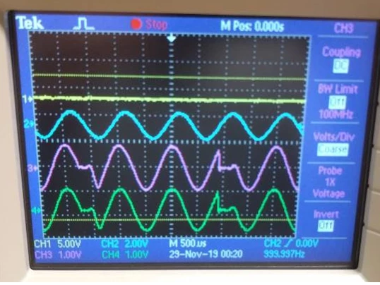
(blue: Input, 1Vpp, 1kHz. green/pink: Line Out L/R)
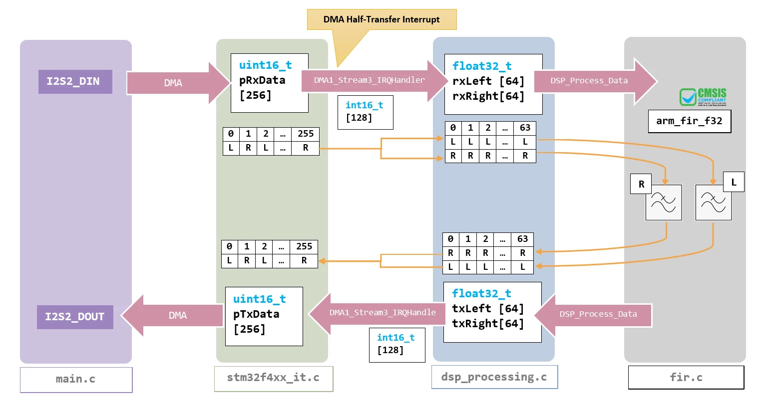
I suspect that this happens because I execute the FIR filter inside the DMA ISR - which is not the way to do it. The next step is to implement a buffering method to run the FIR-Filter not FFT (as in the comments) n the main loop.
How can this be achieved? What is good practice? Is there an app-note or a white paper explaining how to implement a buffer for this application?
My 1st approach: (main and interrupt)
// main.c


/* USER CODE BEGIN PV */
// four alternating buffers
uint16_t pTxRxData_A[DSP_BUFFERSIZE];
uint16_t pTxRxData_B[DSP_BUFFERSIZE];
uint16_t pTxRxData_C[DSP_BUFFERSIZE];
uint16_t pTxRxData_D[DSP_BUFFERSIZE];

// a Merry go Around for the three buffers, containing the pointer to the first element
volatile uint16_t* buffer_merry_go_around[4] = {pTxRxData_A, pTxRxData_B, pTxRxData_C, pTxRxData_D};
volatile uint8_t pDataIndex_Rx = 3;
volatile uint8_t pDataIndex_DSP_in = 2; // increment to get Rx buffer
volatile uint8_t pDataIndex_DSP_out = 1; //
volatile uint8_t pDataIndex_Tx = 0; // increment to get DSP buffer
volatile uint8_t newDataReadyFlag = 0; // ISR Flag to main

/* USER CODE BEGIN 3 */
/* Use MAIN Loop to process buffered Data */
if(newDataReadyFlag){
	newDataReadyFlag = 0;
	DSP_Process_Data((uint16_t*)buffer_merry_go_around[pDataIndex_DSP_in], (uint16_t*)buffer_merry_go_around[pDataIndex_DSP_out], DSP_BLOCK_SIZE);
}
// stm32f4xx_it.c

/**
 * @brief This function handles DMA1 stream4 global interrupt.
 */
void DMA1_Stream4_IRQHandler(void)
{
 /* USER CODE BEGIN DMA1_Stream4_IRQn 0 */
	dmaTransferComplete ++;

 /* USER CODE END DMA1_Stream4_IRQn 0 */
 HAL_DMA_IRQHandler(&hdma_spi2_tx);
 /* USER CODE BEGIN DMA1_Stream4_IRQn 1 */
	HAL_I2S_DMAStop(&hi2s2);
	pDataIndex_Rx = (pDataIndex_Rx+1) % 4;
	pDataIndex_Tx = (pDataIndex_Tx+1) % 4;
	pDataIndex_DSP_in = (pDataIndex_DSP_in+1) % 4;
	pDataIndex_DSP_out = (pDataIndex_DSP_out+1) % 4;

	HAL_I2S_DMAStop(&hi2s2);
	HAL_I2SEx_TransmitReceive_DMA(&hi2s2, (uint16_t*)buffer_merry_go_around[pDataIndex_Tx], (uint16_t*)buffer_merry_go_around[pDataIndex_Rx], DSP_BUFFERSIZE);
	newDataReadyFlag ++;
}
This turns out to be even worse. The passthrough functionality now too has gaps and the FIR amplitude stays the same. This is why I suspect, that the buffers are getting confused somewhere. (e.g. DMA output buffer is not FIR output)
My second approach is similar, with two alternating buffer arrays[2].
Both approaches can be found here:
https://github.com/mnemocron/P5-DSP-Board-mdk/tree/rotating-buffers/Src
https://github.com/mnemocron/P5-DSP-Board-mdk/tree/switching-buffers/Src