Yang Yang
Associate III
August 22, 2026
Solved

USB pins are very vulnerable to ESD events on STM32U595

  • August 22, 2026
  • 5 replies
  • 55 views

Hello, ST experts


It is found that PA12&PA11(USB_D+&USB_D-) are vulnerable to ESD events. In our design the two pins are exposed as external contact point in the shell. Even external ESD diodes(e.g. PESD2USB3UV) are used to protect these pins, 8kV ESD pulse can do damage to these pins, I think that is because the failure of internal diode. So what should do to protect these pins from ESD pulses?


Best Regards

Yang

Best answer by AScha.3

I would say: bad idea , dont do this.

A high speed connection going straight to a cpu , that can be touched by anything....no way to go.

Why not using a standard usb-A port , with grounded metal around, as everybody is using?

dc7af289-0614-de0c-bc97-48e5503dfeed.png

If you insist on a game: > how long will it survive <  --- ok, try with as much protection as possible.

Your PESD2USB3UV triggers at 8V -- the U595 might not survive the first test pulse.

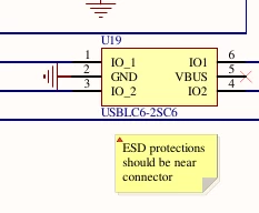
I use the esd-diode device , thats on nucleo boards : (vbus connected to usb V+ )

bc82ff9e-5452-27e6-d43a-395fa621ab92.png

+ your diode at input + small resistor (33 r , or so) close to the input contact points (to reduce current peak to the usbcl6) ---- then try to kill it. It has to survive > 10kV body discharge, 100 times, as this is easily reached in real world.

If you loose the game, take a usb-A port + usblc6 protector. (This combination works on more than 500 boards at my company.)

5 replies

Andrew Neil
Super User
August 22, 2026

Please show your schematic - see: 

 How to write your question to maximize your chances to find a solution 


Did you consult AN4879, Introduction to USB hardware and PCB guidelines using STM32 MCUs ?

Section 2.3 addresses this very issue:

d1297a3e-71b7-6f52-61d7-7e72abd3bdd7.png


This was referenced in your previous thread: 

How to do ESD protection to USB_D+ and USB_D- when USBPHY is not powered for STM32U595VJT6


Also, as  @AScha.3  suggested, look at how it's done on ST boards.

In fact, it's not really specific to ST or STM32: any microcontroller's pins would need protection if they're externally accessible - especially in such an open form as this!

A complex system that works is invariably found to have evolved from a simple system that worked.A complex system designed from scratch never works and cannot be patched up to make it work.
Yang Yang
Yang YangAuthor
Associate III
August 22, 2026

Hello, Neil


I am very appreciated for your help. I will review the hardware design to see if  I can make some changes about this problem.


BR

Yang

AScha.3
Super User
August 22, 2026

Hi,

>In our design the two pins are exposed as external contact point in the shell.

What is "exposed" ? can touch with finger ?   

>So what should do to protect these pins from ESD pulses?

Have a standard USB port with grounded metal surround, as most designs using.

So first "touch"/contact /discharge is always on this , not on any data connects.


If you feel a post has answered your question, please click on " Best Answer ".
Yang Yang
Yang YangAuthor
Associate III
August 22, 2026

Hi? AScha


Yes?it can be touched with finger easily as below. The middle two pins are USB pins. Is there any suggestion with this structure?

285257f6-6c3c-08ed-53c3-d0b2b9a56872.jpeg


BR

Yang


AScha.3
AScha.3Best answer
Super User
August 22, 2026

I would say: bad idea , dont do this.

A high speed connection going straight to a cpu , that can be touched by anything....no way to go.

Why not using a standard usb-A port , with grounded metal around, as everybody is using?

dc7af289-0614-de0c-bc97-48e5503dfeed.png

If you insist on a game: > how long will it survive <  --- ok, try with as much protection as possible.

Your PESD2USB3UV triggers at 8V -- the U595 might not survive the first test pulse.

I use the esd-diode device , thats on nucleo boards : (vbus connected to usb V+ )

bc82ff9e-5452-27e6-d43a-395fa621ab92.png

+ your diode at input + small resistor (33 r , or so) close to the input contact points (to reduce current peak to the usbcl6) ---- then try to kill it. It has to survive > 10kV body discharge, 100 times, as this is easily reached in real world.

If you loose the game, take a usb-A port + usblc6 protector. (This combination works on more than 500 boards at my company.)

If you feel a post has answered your question, please click on " Best Answer ".