Solved
USART with DMA circular buffer transfer only the first byte
Hello,
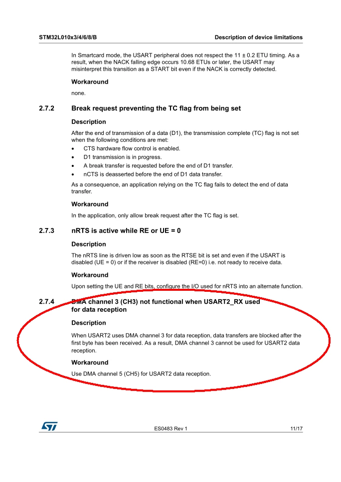
I have to transfer the bytes received from UART2 to the circular buffer via DMA. The microcontroller I am using is STM32L010F4 with LL instead of HAL.
When I send a sequence of bytes to UART2 I notice that only the first byte is loaded into the buffer and the UART IDLE interrupt is triggered.
Every time I send a sequence of bytes the IDLE interrupt is triggered but in the buffer I always see only the first byte.
Thanks!
#define ARRAY_LEN(x) (sizeof(x) / sizeof((x)[0]))

DMADataCallback _dataCallback;
static uint8_t _usartRxDmaBuffer[64];
/* USER CODE END 0 */

/* USART2 init function */

void USART_Init(DMADataCallback callback)
{
	_dataCallback = callback;

	LL_USART_InitTypeDef USART_InitStruct = {0};
 LL_GPIO_InitTypeDef GPIO_InitStruct = {0};

 /* Peripheral clock enable for UART and DMA */
 LL_APB1_GRP1_EnableClock(LL_APB1_GRP1_PERIPH_USART2);
 LL_IOP_GRP1_EnableClock(LL_IOP_GRP1_PERIPH_GPIOA);
 LL_AHB1_GRP1_EnableClock(LL_AHB1_GRP1_PERIPH_DMA1);

	/**
	* USART2 GPIO Configuration
 * PA2 ------> USART2_TX
 * PA3 ------> USART2_RX
 */
 GPIO_InitStruct.Pin = LL_GPIO_PIN_2;
 GPIO_InitStruct.Mode = LL_GPIO_MODE_ALTERNATE;
 GPIO_InitStruct.Speed = LL_GPIO_SPEED_FREQ_VERY_HIGH;
 GPIO_InitStruct.OutputType = LL_GPIO_OUTPUT_PUSHPULL;
 GPIO_InitStruct.Pull = LL_GPIO_PULL_NO;
 GPIO_InitStruct.Alternate = LL_GPIO_AF_4;
 LL_GPIO_Init(GPIOA, &GPIO_InitStruct);

 GPIO_InitStruct.Pin = LL_GPIO_PIN_3;
 GPIO_InitStruct.Mode = LL_GPIO_MODE_ALTERNATE;
 GPIO_InitStruct.Speed = LL_GPIO_SPEED_FREQ_VERY_HIGH;
 GPIO_InitStruct.OutputType = LL_GPIO_OUTPUT_PUSHPULL;
 GPIO_InitStruct.Pull = LL_GPIO_PULL_NO;
 GPIO_InitStruct.Alternate = LL_GPIO_AF_4;
 LL_GPIO_Init(GPIOA, &GPIO_InitStruct);

 /* USART2 DMA init */
 LL_DMA_SetPeriphRequest(DMA1, LL_DMA_CHANNEL_3, LL_DMA_REQUEST_4);
 LL_DMA_SetDataTransferDirection(DMA1, LL_DMA_CHANNEL_3, LL_DMA_DIRECTION_PERIPH_TO_MEMORY);
 LL_DMA_SetChannelPriorityLevel(DMA1, LL_DMA_CHANNEL_3, LL_DMA_PRIORITY_VERYHIGH);
 LL_DMA_SetMode(DMA1, LL_DMA_CHANNEL_3, LL_DMA_MODE_CIRCULAR);
 LL_DMA_SetPeriphIncMode(DMA1, LL_DMA_CHANNEL_3, LL_DMA_PERIPH_NOINCREMENT);
 LL_DMA_SetMemoryIncMode(DMA1, LL_DMA_CHANNEL_3, LL_DMA_MEMORY_INCREMENT);
 LL_DMA_SetPeriphSize(DMA1, LL_DMA_CHANNEL_3, LL_DMA_PDATAALIGN_BYTE);
 LL_DMA_SetMemorySize(DMA1, LL_DMA_CHANNEL_3, LL_DMA_MDATAALIGN_BYTE);

 LL_DMA_SetPeriphAddress(DMA1, LL_DMA_CHANNEL_3, (uint32_t)&USART2->RDR);
 LL_DMA_SetMemoryAddress(DMA1, LL_DMA_CHANNEL_3, (uint32_t)_usartRxDmaBuffer);
 LL_DMA_SetDataLength(DMA1, LL_DMA_CHANNEL_3, ARRAY_LEN(_usartRxDmaBuffer));

 /* Enable HT & TC interrupts */
 LL_DMA_EnableIT_HT(DMA1, LL_DMA_CHANNEL_3);
 LL_DMA_EnableIT_TC(DMA1, LL_DMA_CHANNEL_3);

 /* DMA interrupt init */
 NVIC_SetPriority(DMA1_Channel2_3_IRQn, 0);
 NVIC_EnableIRQ(DMA1_Channel2_3_IRQn);

 /* USART2 configuration */
 USART_InitStruct.BaudRate = 115200;
 USART_InitStruct.DataWidth = LL_USART_DATAWIDTH_8B;
 USART_InitStruct.StopBits = LL_USART_STOPBITS_1;
 USART_InitStruct.Parity = LL_USART_PARITY_NONE;
 USART_InitStruct.TransferDirection = LL_USART_DIRECTION_TX_RX;
 USART_InitStruct.HardwareFlowControl = LL_USART_HWCONTROL_NONE;
 USART_InitStruct.OverSampling = LL_USART_OVERSAMPLING_16;
 LL_USART_Init(USART2, &USART_InitStruct);
 LL_USART_ConfigAsyncMode(USART2);
 LL_USART_EnableDMAReq_RX(USART2);
 LL_USART_EnableIT_IDLE(USART2);

 /* USART interrupt */
 NVIC_SetPriority(USART2_IRQn, 0);
 NVIC_EnableIRQ(USART2_IRQn);

 /* Enable USART and DMA */
 LL_DMA_EnableChannel(DMA1, LL_DMA_CHANNEL_3);
 LL_USART_Enable(USART2);
}

/* USER CODE BEGIN 1 */
void DMA_RX_Check(void)
{
	static size_t old_pos;
 size_t pos;

 /* Calculate current position in buffer */
 pos = ARRAY_LEN(_usartRxDmaBuffer) - LL_DMA_GetDataLength(DMA1, LL_DMA_CHANNEL_3);
 if (pos != old_pos)
	{	/* Check change in received data */
		if (pos > old_pos)
		{	/* Current position is over previous one */
			/* We are in "linear" mode */
 /* Process data directly by subtracting "pointers" */
 _dataCallback(&_usartRxDmaBuffer[old_pos], pos - old_pos);
 }
		else
		{
			/* We are in "overflow" mode */
			/* First process data to the end of buffer */
			_dataCallback(&_usartRxDmaBuffer[old_pos], ARRAY_LEN(_usartRxDmaBuffer) - old_pos);
			/* Check and continue with beginning of buffer */
			if (pos > 0)
				_dataCallback(&_usartRxDmaBuffer[0], pos);
 }
	}
 old_pos = pos;	/* Save current position as old */

 /* Check and manually update if we reached end of buffer */
 if (old_pos == ARRAY_LEN(_usartRxDmaBuffer))
		old_pos = 0;
}
void DMA1_Channel2_3_IRQHandler(void)
{
/* Check half-transfer complete interrupt for DMA1 (UART2) */
if (LL_DMA_IsEnabledIT_HT(DMA1, LL_DMA_CHANNEL_3) && LL_DMA_IsActiveFlag_HT3(DMA1)) {
LL_DMA_ClearFlag_HT3(DMA1); /* Clear half-transfer complete flag */
DMA_RX_Check(); /* Check for data to process */
}
/* Check transfer-complete interrupt for DMA1 (UART2) */
if (LL_DMA_IsEnabledIT_TC(DMA1, LL_DMA_CHANNEL_3) && LL_DMA_IsActiveFlag_TC3(DMA1)) {
LL_DMA_ClearFlag_TC3(DMA1); /* Clear transfer complete flag */
DMA_RX_Check(); /* Check for data to process */
}
}
void USART2_IRQHandler(void)
{
/* Check for IDLE line interrupt */
if (LL_USART_IsEnabledIT_IDLE(USART2) && LL_USART_IsActiveFlag_IDLE(USART2)) {
LL_USART_ClearFlag_IDLE(USART2); /* Clear IDLE line flag */
DMA_RX_Check(); /* Check for data to process */
}
}