
Associate II
September 8, 2023
Question

Unable to program STM32F103 through UART

  • September 8, 2023
  • 13 replies
  • 11041 views

I created a custom board with the STM32 (F103C8T6), and I am trying to program it using a FTDI USB to Serial module. However, nothing is happening, it doesn't seem to be sending anything and when I try using STM32CubeProgrammer it says:
Timeout error occured while waiting for acknowledgement.
Error: Activating device: KO. Please, verify the boot mode configuration and check the serial port configuration. Reset your device then try again...

Relevant schematics:
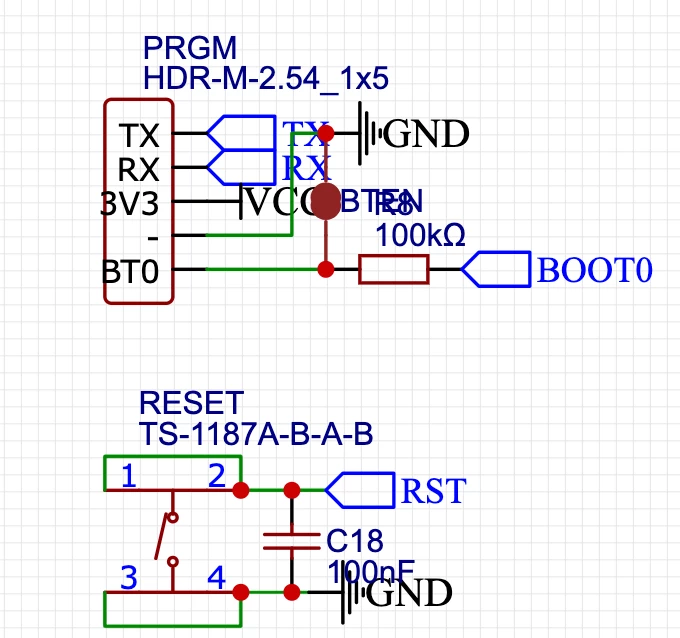


Nv7_2-1694149065260.png

Note that BTEN is unconnected and the BT0 header pin is connected to VCC (which should put it into boot mode).
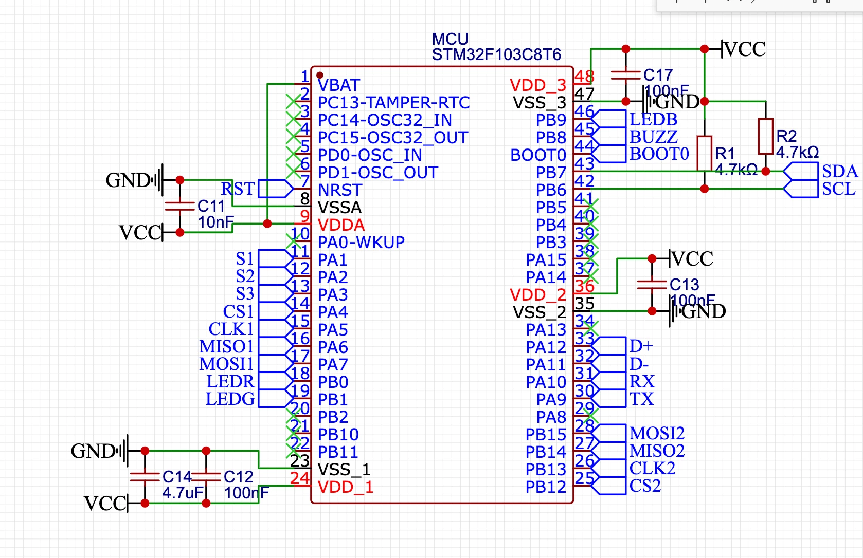
 

Nv7_4-1694149113730.png

I have tried reversing RXD and TXD and both 9600 and 115200 baud rate. How can I debug this?

 

This topic has been closed for replies.

13 replies

Issamos
Super User
September 8, 2023

Hello @Nv7 

This post can be helpful for your case.

Best regards.

II

Tesla DeLorean
Guru
September 8, 2023

Check part orientation 

Check level on NRST

Check RX/TX sense. The STM32 TX should go to the FTFI RX.

Use 8E1 with 0x7F data pattern.

Check connectivity with SWD/JTAG.

Check BOOT0 and BOOT1 levels.

Tips, Buy me a coffee, or three.. PayPal Venmo (See Profile) Up vote any posts that you find helpful, it shows what's working..
Nv7Author
Associate II
September 8, 2023

- NRST is LOW when button pressed, HIGH when button isn't pressed
- I tried both directions but I did what you said first
- What is 8E1 with 0x7F?
- I didn't get a SWD programmer because I was hoping to program via serial
- BOOT0 is HIGH, BOOT1 is floating

waclawek.jan
Super User
September 8, 2023

Is it a genuine STM32F103, or a blue pill?

JW

Nv7Author
Associate II
September 8, 2023

It is a STM32F103C8T6 I got assembled from JLCPCB. I am pretty sure it is genuine, but it is on a custom design of mine

RomainR.
ST Employee
September 8, 2023

Hello @Nv7 

I think what is missing in your design is a header connector for the Serial Wire Debugger on the dedicated IO's:
PA13 SWDIO
PA14 SWDCLK
You could establish a connection with a STLink and the STM32CubeProgrammer in SWD mode to validate that your MCU is programmable/Option Bytes readable and therefore "debug" possible.
This step will allow you to validate the power supply integrity of your PCB (all VDD/VSS and VDDA/VSSA are properly connected and your MCU is correctly powered)
After that, testing the STM32 in bootloader will be your next step.

You can refer to AN2586 Getting started with STM32F10xxx hardware development in section 4 Boot configuration.
Getting started with STM32F10xxx hardware development - undefined

BR
romain,

To give better visibility on the answered topics, please click on Accept as Solution on the reply which solved your issue or answered your question.
Nv7Author
Associate II
September 8, 2023

Unfortunately this board doesn't have SWD debugging since we were expecting to program it via serial. Can we do anything through serial?

RomainR.
ST Employee
September 8, 2023

In your design BOOT1 is floating, internal bootloader cannot works.
Again, you should review your design and refer in AN2586 Chapter 4 Boot Configuration.
To enter in Bootloader (System memory in the Table 2 below) you must apply on pins BOOT0 = 1 (VCC) and BOOT1 = 0 (GND).
BR
Romain,

RomainR_0-1694182727854.png


To give better visibility on the answered topics, please click on Accept as Solution on the reply which solved your issue or answered your question.
Nv7Author
Associate II
September 9, 2023

Shouldn't it still work right now because the flash memory is empty?

waclawek.jan
Super User
September 9, 2023

No, only newer STM32 have this feature. Read AN2606.

JW

Nv7Author
Associate II
October 22, 2023

Ok, I soldered BOOT1 to GND, but its still not doing anything. Any ideas on what else it could be?

Tesla DeLorean
Guru
October 22, 2023

Outside of STM32 Cube Programmer you can use RealTerm, or other similar terminal applications, to send the 0x7F pattern at 9600 8E1  (8-bit, Even Parity, 1 stop bit), the expected response is 0x79. This is a on-shot connection method, where the system tries to compute the baud rate from the bit pattern. If this fails, reset and try again.

If it's non-responsive, it generally points to an electrical or circuit issue.

Normally people also provide a means for SWD/JTAG connectivity to program/debug products.

You might be able to connect via USB, in DFU mode, where the device would come up as a "STM32 BOOT DEVICE" type entity in Windows from the System Memory loader in the STM32F1

A picture might help confirm orientation, and counterfeit devices.

Tips, Buy me a coffee, or three.. PayPal Venmo (See Profile) Up vote any posts that you find helpful, it shows what's working..